


Overview |
1
1
Overview
1.1
General Description
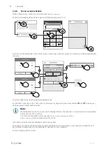
This manual describes basic information how to operate and perform maintenance on the unit and the system it is con-
nected to.
Read the instructions carefully and in its entirety.
For description of advanced settings and installation of accessories see
Service and Accessories Installation manual
.
All documents can be found in our online catalogue at
www.systemair.com
.
1.2
Warranty
For the assertion of warranty claims, the products must be correctly connected and operated, and used in accordance
with the data sheets. Further prerequisites are a completed maintenance plan with no gaps and a commissioning re-
port. Systemair will require these in the case of a warranty claim.
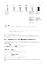
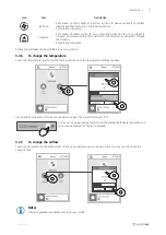
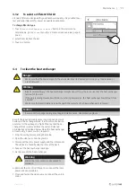
1.3
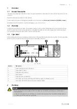
Type label
Before calling your service representative, make a note of the specification and production number from the type label,
which can be found next to the external connections and inside of the unit.
SAVE-P
Fig. 1 Type label
Position
Description
1
Product code (product specification)
2
Product item number
3
Production order number
4
Serial number
5
Production date (YY.MM.DD)
6
Scannable code for manufacturing order (MO) number and software version
7
Scannable code for the spare parts list and documentation
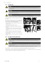
2
Warnings
Danger
• Make sure that the mains supply to the unit is disconnected before performing any maintenance or
electrical work!
• All electrical connections and maintenance work must be carried out by an authorized installer and in
accordance with local rules and regulations.
271400 | v1.0


