


40/69 |
F-B90
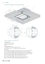
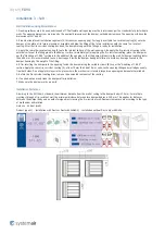
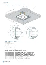
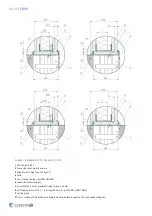
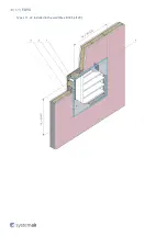
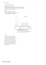
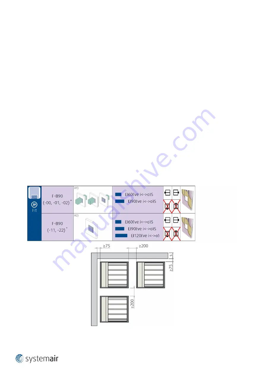
Installation 3F – Fitted
Wall Installation Using Mineral Wool, without Gap
1. Opening surfaces must be even and cleaned off. The flexible wall opening must be reinforced as per the standards for plasterboard
walls. The opening dimensions are based on the nominal dimensions of the damper with added clearance. The opening will have the
dimensions of W1 and H1.
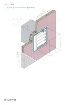
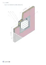
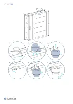
2. Prepare mineral wool installation segments (3; thickness as opening gap). First apply a suitable fire-resistant coating (5) onto the
damper at the place of its future placement, assemble and glue the filling of the future installation with the same fire-resistant
coating. After the fire-resistant coating has dried, the damper along with the filling are ready for installation.
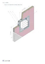
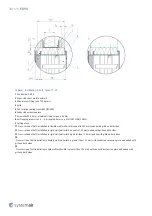
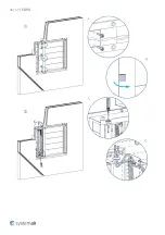
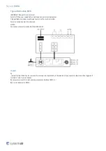
3. Apply the same fire-resistant coating (5) onto the internal surface of the wall opening. Also apply the fire-resistant coating to the
external surface of the filling glued to the damper surface. Immediately after applying the fire-resistant coating, place the damper as
per the “Handling of F-B90” section into the middle of the opening so that the damper blade is in the wall. For damper widths greater
than 600 mm, it is recommended to use a duct support inside the damper during installation to avoid any damage caused to the
damper housing by the weight of the filling.
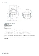
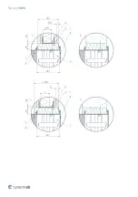
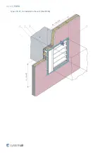
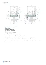
4. After inserting the damper into the opening, fasten the damper using the suitable screws (8) as per the “Handling of F-B90”
section. Apply the same fire-resistant coating (5), at least 2 mm thick and 10 mm wide, to the opening filling and wall edges evenly
from both sides. Do not apply this layer in the place where the mechanism is located, inspection openings and manufacturer labels.
5. Before the fire-resistant coating dries, remove the unwanted remnants of the coating.
6. If needed, uncover and clean the damper after installation.
7. Make sure the damper works properly.
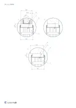
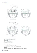
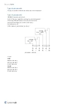
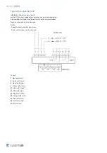
Installation Distances
According to the EN 1366-2 standard, the minimum distance from the wall or ceiling to the damper body is 75 mm. For multiple
crossings through a fire-resistant wall, the minimum distance between two damper bodies is 200 mm. This applies for distances
between the damper body and a nearby foreign object crossing the fire-resistant wall. Damper clearances vary according to the type
of mechanism and rotation.
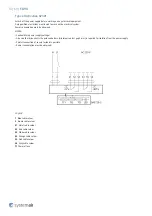
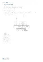
Notes:ve - Vertical (wall)
Product typeA1) - Installation with Ducts or Duct with GrilleA2) - Installation without Duct, only with Grille
Summary of Contents for F-B90
Page 1: ...F B90 Multiblade Fire damper ...
Page 14: ...14 69 F B90 Dimensions Free area ...
Page 15: ...15 69 F B90 Dimensions ...
Page 16: ...16 69 F B90 Weights ...
Page 17: ...17 69 F B90 ...
Page 18: ...18 69 F B90 ...
Page 23: ...23 69 F B90 Types 00 01 02 installed in the wall Max EI90S ...
Page 24: ...24 69 F B90 ...
Page 28: ...28 69 F B90 Types 11 22 installed in the wall Max EI90S EI120 ...
Page 29: ...29 69 F B90 ...
Page 32: ...32 69 F B90 Types 00 01 02 installed in the wall Max EI90S ...
Page 33: ...33 69 F B90 ...
Page 37: ...37 69 F B90 Types 11 22 installed in the wall Max EI90S EI120 ...
Page 38: ...38 69 F B90 ...
Page 41: ...41 69 F B90 Types 00 01 02 installed in the wall Max EI90S ...
Page 44: ...44 69 F B90 Types 11 22 installed in the wall Max EI90S EI120 ...
Page 47: ...47 69 F B90 ...
Page 48: ...48 69 F B90 ...
Page 49: ...49 69 F B90 ...
Page 61: ...61 69 F B90 Operation manual ...
Page 62: ...62 69 F B90 ...
Page 63: ...63 69 F B90 ...
Page 64: ...64 69 F B90 ...
Page 66: ...66 69 F B90 ...
Page 69: ...Systemair DESIGN 2020 10 07 HandBook_F_B90_en GB 1D2E1FF0 E010 11EA E8DD 8BBB7258CB9B ...