


7
8
Installation
Safety information
♦
Observe 2
♦
Check the surface before installation for load bearing capacity.
♦
Consider all static and dynamic loads when selecting hoisting equipment and fastening components.
♦
Provide contact and intake protection and ensure safety distances according to DIN EN ISO13857 and DIN 24167-1.
Preconditions
♦
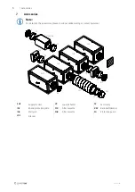
Ensure that the fan and all its components are
undamaged.
♦
Fit the fans in such a way that there is sufficient
access for installation, troubleshooting, maintenance
and repair.
♦
Protect against dust and moisture when installing.
♦
Ensure that the information on the name plates (fan
and motor) matches up with the operating conditions.
♦
A warning sign must be attached close to the air
outlet, stating that the air outlet must not be covered.
Important
Damage to the bearings or other parts of the fan
can occur.
♦
Do not place a duct bend directly before or
after the fan!
♦
Ensure a smooth and constant air flow to the
device.
min.
2,5x
ØDN
min.
2,5x ØDN
ØDN
• Round duct system:
D
= Nominal diameter
• Rectangular duct system:
D
= Hydraulic diameter
TFK Temperature sensor
The distance between the TFK Temperature sensor and the SUE must be at least 1 meter.
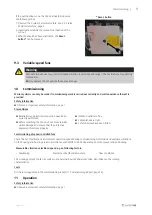
Installation positions
The inspection opening* of the SUE can be freely placed
upwards or sidewards.
Important
The overheating protection may not work
correctly!
♦
Do not place the inspection opening*
downwards.
1°
179°
*
If the SUE is equipped with a drain plug:
Important
Damage to the fan if condensation water cannot drain.
♦
Ensure that the drain plug is always at the lowest point of the fan to ensure that the condensation water
can drain.
199495 | 001
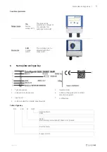
Summary of Contents for 94729
Page 4: ......