


[4.2]DETERMINE MOUNTINg LOCATION AND CONfIgURATION
On ducts wider than 18 inches it is recommended that the detector be
mounted downstream of a bend, obstruction in the duct, or the supply or
return air inlet.
Exception: Installation of duct detectors can be on or within a commercial
packaged rooftop heating and air-conditioning system, fire/smoke dampers
and economizers. They may be mounted in either the supply and/or return air
section as determined by local code.
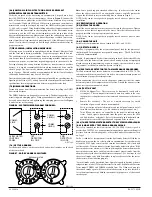
Once a suitable location is selected, determine if the detector is to be mounted
in a side-by-side “rectangular” configuration or a top-over-bottom “square”
configuration as shown in Figure 2. If mounting in the square configuration,
remove the rear attachment screw, rotate the unit at hinge, and replace the
screw into the new attachment hole as shown in Figure 2. Do NOT remove the
hinge screw during this process. Final installation approval shall be based
upon passing differential pressure and smoke entry tests described in the Mea-
surement Tests section.
fIgURE 2:
REMOVE SCREW AND PIVOT
DETECTOR AS SHOWN BELOW.
REPLACE SCREW
TO SECURE DETECTOR
IN PLACE.
H0550-00
[4.3]DRILL ThE MOUNTINg hOLES
Remove the paper backing from the mounting template supplied. Affix the
template to the duct at the desired mounting location. Make sure the template
lies flat and smooth on the duct.
[4.3.1]fOR RECTANgULAR SIDE-By-SIDE MOUNTINg CONfIgURATION:
Center punch at (4) target centers: (2) “A” for sampling tubes and (2) “B” for
the rectangular configuration mounting tabs as shown on mounting template.
Drill pilot holes at target “A” centers and cut two 1.375 inch diameter holes
using a
13
⁄
8
inch hole saw or punch. Drill .156 inch diameter holes using a
5
⁄
32
inch drill at target “B” centers.
[4.3.2]fOR SqUARE TOP-OVER-BOTTOM MOUNTINg CONfIgURATION:
Center punch at (4) target centers: (2) “A” for sampling tubes and (2) “C” for
the square configuration mounting tabs as shown on mounting template. Drill
pilot holes at target “A” centers and cut two 1.375 inch diameter holes using
a 1
3
⁄
8
inch hole saw or punch. Drill .156 inch diameter holes using a
5
⁄
32
inch
drill at target “C” centers. If desired, drill an additional .156 inch hole at the
location of one of the mounting tabs on the lower housing.
[4.4]SECURE ThE DUCT DETECTOR TO ThE DUCT
Use two (rectangular configuration) or three (square configuration) of the pro-
vided sheet metal screws to screw the duct detector to the duct.
CAUTION: Do not overtighten the screws.
[5]SAMPLINg TUBE INSTALLATION
[5.1]SAMPLINg TUBE SELECTION
The sampling tube must be purchased separately. Order the correct length,
as specified in Table 1, for width of the duct where it will be installed. The
sampling tube length must extend at least
2
/
3
across the duct width for optimal
performance.
The sampling tube is always installed with the air inlet holes facing into the
air flow. To assist proper installation, the tube’s connector is marked with an
arrow. Make sure the sampling tube is mounted so that the arrow points into
the airflow as shown in Figure 3. Mounting the detector housing in a vertical
orientation is acceptable provided that the air flows directly into the sam-
pling tube holes as indicated in Figure 3. The sampling tube and exhaust tube
can be mounted in either housing connection as long as the exhaust tube is
mounted downstream from the sampling tube.
SS-300-018
2
I56-3371-003R
fIgURE 1. ExPLODED VIEW Of DUCT SMOkE DETECTOR COMPONENTS:
H0569-00
EXHAUST TUBE
SENSOR HEAD
SENSOR MODULE COVER
WIRING COMPARTMENT COVER
WIRING COMPARTMENT
SENSOR MODULE
SAMPLING
TUBE
NOTE: SENSOR HEAD IS ONLY
INCLUDED ON SPECIFIED MODELS.
SOLD
SEPERATELY


