5
systembuild.com
Board
Identification
Not
actual
size
Tube
You
This piece is paperboard construction.It is not made from wood, but isrequired for the assembly of your unit.
A
B
C
F
E
D
G
Page 1: ...RUCTION BOOKLET CONTAINS IMPORTANT SAFETY INFORMATION PLEASE READ AND KEEP FOR FUTURE REFERENCE WARNING For the latest information on SystemBuild products follow us at Ameriwood Home Tube You Date of...
Page 2: ...and count the parts before attempting assembly Compression dowels are lightly tapped in with a hammer Slides are labeled with a R right and L left for proper placement Make sure to always face the poi...
Page 3: ...carefully and follow the proper order Separate and count all your parts and hardware Give yourself enough room for the assembly process Have the following tools Flat Head Screwdriver 2 Phillips Head S...
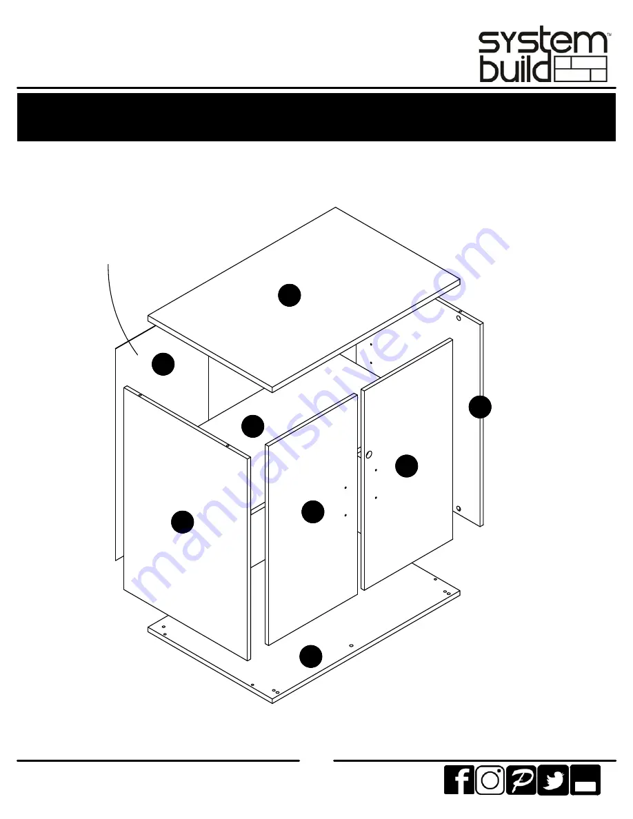
Page 4: ...ece is paperboard construction It is not made from wood but is required for the assembly of your unit 2 End Panels 37466056010 Top 37466056020 Bottom 37466056030 Left Door 37466056050 Right Door 37466...
Page 5: ...5 systembuild com Board Identification Not actual size Tube You This piece is paperboard construction It is not made from wood but is required for the assembly of your unit A B C F E D G A...
Page 6: ...0 cam lock x8 A22510 cam bolt x8 A12105 7 16 pan head x2 A11145 1 2 flat head x2 A11210 3 4 pan head x4 A17300 3 4 screw x28 A21110 nail x4 A80250 shelf support x4 A43100 base glide x1 A55410 latch x1...
Page 7: ...7 systembuild com STEP1 x4 A22510 Attach four cam bolt and the two plastic catches to the top B as shown x2 A30030 x4 A12105 B...
Page 8: ...P2 x4 A22510 x4 A43100 C C bottom surface unfinished surface top surface finished surface Attach the four base glides to the bottom surface of the bottom C Attach four cam bolts to the top surface of...
Page 9: ...9 systembuild com STEP3 Proper orientation of CAM LOCK Tip Assembly Quick x8 A22570 Insert four cam locks into both end panels A as shown x2 A...
Page 10: ...10 systembuild com STEP4 Attach the top B and bottom C to the end panels A as shown UNLOCK LOCK raw edges are shaded A A B C...
Page 11: ...stance from corner to corner must be equal as shown Flush the bottom edge of the back panel G with the bottom edge of the bottom C Attach the back panel as shown nailing straight into the raw edges IM...
Page 12: ...tic catch latch and handle as shown Use the hinge kit screws for the hinge Use the 7 16 for the plastic catch and 3 4 pan head for the latch Be sure the hinge pin is to the outside as shown x1 A55410...
Page 13: ...30 x1 A61000 x2 A11145 1 2 x1 A55015 Be sure the hinge pin is to the outside as shown Attach hinge plastic catch lock and handle as shown Use the hinge kit screws for the hinge Use the 7 16 screws for...
Page 14: ...lding onto the door insert the top hinge and the bushing into the hole in the top B Slide the bottom edge of the door into the bottom hinge and fasten with two screws as shown Repeat for the other doo...
Page 15: ...15 systembuild com STEP9 x4 A80250 Insert the shelf support at the preferred level and place the adjustable shelf D onto the shelf supports D...
Page 16: ...so that the plastic catches engage Extend the barrel of the latch down into the hole in the bottom shelf 2 Close the right door so the plastic catches engage Insert the key into the lock and turn This...
Page 17: ...applies to compliance of this product with the CPSC Ban on Lead Containing Paint 16 CFR 1303 3 This product is distributed by Dorel Home Furnishings Inc 410 East First Street South Wright City MO 633...
Page 18: ...deals and discount codes Quick and easy replacement part service To register your product visit systembuild com Visit your local retailer s website rate your purchased product and leave us some feedba...
Page 19: ...R derecha y L izquierda para la colocaci n correcta Aseg rese de que siempre este el punto locaizado en la parte superior de bloqueador de leva este volteadohacia borde exterior Utilizar todos los cl...
Page 20: ...dad est derecha La distancia de esquina a esquina debe ser igual como se muestra Alinea el panel trasero G con el borde inferior del fondo C Une el panel trasero como se muestra clavando directamente...
Page 21: ...uerta derecha primero de manera que las agarraderas conecten Inserta la llave en la cerradura y gira Esto posicionar el rodillo de la cerradura detr s de la puerta izquierda Retira la llave P gina 17...
Page 22: ...s glissi res sont marqu es d un R droit et d un L gauche pour un bon placement Assurez vous toujours de faire face la pointe situ sur le haut de la Serrure de Came vers le bord ext rieur Utiliser tous...
Page 23: ...re quivalente tel que d montr galiser l extr mit inf rieure du panneau arri re G avec l extr mit inf rieure du bas C Attacher le panneau arri re tel que d montr en clouant directement dans les bordure...
Page 24: ...Ins rer la cl dans la serrure et tourner Cela positionnera la barre de verrouillage derri re la porte gauche Retirer la cl Page 17 CHARGES MAXIMALES Ce meuble a t con u pour supporter les charges max...