background image


14

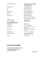
Function 

Auto/Man Shutter Control(E.S.) :                    Auto(On), Man(Off) (Dip Switch) 

Manual Shutter Control :                                1/60(1/50), 1/100(1/120), 1/250, 

1/500, 1/1000, 1/2000, 1/4000, 
1/10,000(Dip Switch)  

Flickerless(F.F) :                                            ON/OFF (Dip Switch) 

BLC :                                                             ON/OFF (Dip Switch) 

EI :                                                                ON/OFF (Dip Switch) 

Auto Iris Lens :                                            

DC/Video (Dip Switch) 

AGC Select :                                                  Normal/High (Dip Switch) 

AGC :                                                             ON/OFF (Dip Switch) 

White Balance :                                              ON/OFF (Dip Switch)                

Auto, Quick, Indoor, Outdoor  

Sync :  

Internal / Line Lock (Dip Switch) 

Vert Phase Adjust : 

Adjustable (POT) 

DC Iris Level Adjust :                                      Adjustable (POT) 

Connector and Mechanical 

Video Output : 

BNC Connector 

Power Input : 

3-pin Terminal Block  

AI/DC Output :                                                4-pin mini din jack (Standard 

Connection) 

Lens Mount :                                                  C/CS (Selected through back 

focus) 

Mounting Hole :                                              1/4" UNC Top and Bottom 

External Dimensions :  

2.44W x 2.1H x 5.0D inch  
(62W x 54H x 127D mm) 

Weight : 

9.34oz (265g) 


* High Resolution DSP Color Camera * 

Summary of Contents for HICB355H

Page 1: ...INSTRUCTION MANUAL DSP COLOR CAMERA 1 3 INTERLINE TRANSFER CCD STANDARD RESOLUTION HIGH RESOLUTION Please read this manual thoroughly before use and keep it handy for future reference ...

Page 2: ...ii ISSUE 1 DECEMBER 2004 ...

Page 3: ...ightning flash with arrowhead symbol within an equilateral triangle is intended to alert the user to the presence of uninsulated dangerous voltage within the product s enclosure that may be of sufficient magnitude to constitute a risk of electric shock to persons The exclamation point within an equilateral triangle is intended to alert the user to the presence of important operating and maintenanc...

Page 4: ... THIS EQUIPMENT DOES CAUSE HARMFUL INTERFERENCE TO RADIO OR TELEVISION RECEPTION WHICH CAN BE DETERMINED BY TURNING THE EQUIPMENT OFF AND ON THE USER IS ENCOURAGED TO TRY TO CORRECT THE INTERFERENCE BY ONE OR MORE OF THE FOLLOWING MEASURES REORIENT OR RELOCATE THE RECEIVING ANTENNA INCREASE THE SEPARATION BETWEEN THE EQUIPMENT AND RECEIVER CONNECT THE EQUIPMENT INTO AN OUTLET ON A CIRCUIT DIFFEREN...

Page 5: ...power refer to the operating instructions 8 GROUNDING OR POLARIZATION Equipment that is powered through a polarized plug a plug with one blade wider than the other will fit into the power outlet only one way This is a safety feature If you are unable to insert the plug fully into the outlet try reversing the plug Do not defeat the safety purpose of the polarized plug Alternate Warning If the equip...

Page 6: ... in damage to the unit E If the equipment has been dropped or the casing damaged F When the equipment exhibits a distinct change in performance 14 REPLACEMENT PARTS When replacement parts are required be sure the service technician uses replacement parts specified by the manufacturer or that have the same characteristics as the original part Unauthorized substitutions may result in fire electric s...

Page 7: ... PACKAGE 6 MANUAL IRIS LENS ADJUSTMENT 6 VIDEO TYPE AUTO IRIS LENS INSTALLATION AND ADJUSTMENT 6 DC TYPE AUTO IRIS LENS INSTALLATION AND ADJUSTMENT 8 BACKFOCUS ADJUSTMENT 10 ZOOM LENS BACKFOCUS ADJUSTMENT 11 TROUBLESHOOTING AND MAINTENANCE 12 SPCIFICATIONS 13 vii ...

Page 8: ...THIS PAGE INTENTIONALLY LEFT BLANK viii ...

Page 9: ... 5 lux F1 2 sensitivity Standard 0 8 lux F1 2 sensitivity High C CS backfocus cam for easy adjustment Auto electronic shutter 1 60 1 50 1 100 000 and manual electronic shutter modes Auto and manual white balance modes Compatible with video or DC type lenses with dip switch select Quick connect for video or DC lens with 4 pin connector Flicker less BLC AGC select Normal High AGC Sync adjustments 12...

Page 10: ...Lock Screw Back Focus Ring Camera Mounting Bracket C MOUNT LENS CS MOUNT LENS Function Switch Power LED Power Input Terminal LEVEL PHASE PWR LENS 12VDC 24VAC CLASS 2 VIDEO OUT G V Phase Potentiometer Level potentiometer for DC type A I lens Continued on next page 1 Back focus Lock Screw Allows the user to secure the backfocus setting ...

Page 11: ... switch interval The vertical phase adjustment allows the camera s line lock sync to be adjusted from 0 to 360 degrees with reference to zero line crossing of the AC power source Ensure that all cameras are powered from the same electrical source and wired in a similar fashion Adjust the phase control on the back of the camera until there is no vertical flip or roll on the monitor while using an a...

Page 12: ...cklight compensation When set to ON the camera will automatically try to maintain proper exposure in the specific area even if the lighting level changes E I on off SW1 Auto Exposure When set to the ON position the electronic iris switch automatically varies the camera s shutter to mimic auto iris control allowing fixed or manual iris lenses to be used in a wider range When this switch is set to O...

Page 13: ...white balance Quick ATW Indoor improves the color balance in areas where a mixture of light sources exist Outdoor Improves the color balance in arrears where day light is the main source of light Switch Position SW8 SW9 Mode Switch SW8 9 on on ATW on off AWB off on Indoor off off Outdoor Sync Select Switch int LL Use this switch to set the camera synchronization mode internal int or Line Lock LL 9...

Page 14: ...the lens to the OPEN position and adjust the manual iris for the appropriate range Adjust during the brightest conditions opening the lens to the minimum f stop yielding a good picture under the brightest scene conditions Do not saturate the picture The manual iris is used in indoor applications where lighting from windows can considerably affect the light level of the room VIDEO AUTO IRIS INSTALL...

Page 15: ...e E I switch should be in the OFF position 5 The A I switch should be in the VIDEO position 6 Apply power to the camera 7 Adjust the focus ring on the lens for an optimum picture If a picture is not visible set the lens for proper exposure by adjusting the ALC Automatic Level Control and the level on the lens The ALC setting can range between AVG average or PK peak A midrange setting is appropriat...

Page 16: ...final adjustment of the video level 9 If the auto iris has a gain adjustment and the picture oscillates between open and closed under bright lights slowly turn the gain adjustment counter clockwise until the oscillating stops Increase the light getting to the camera by adjusting the level control and re adjusting the gain control DC AUTO IRIS LENS INSTALLATION ADJUSTMENT The camera supports DC typ...

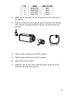
Page 17: ...3 Plug the connector into the auto iris jack on the back of the camera The connector is polarized and can only be inserted into the jack one way BACK VIEW 4 The E I switch should be in the OFF position 5 The A I switch should be in the DC position 6 Apply power to the camera 7 Adjust the auto iris lens for an optimum picture using the LEVEL control on the back of the camera ...

Page 18: ...s visible focus on the picture If the picture is not visible open the iris on the lens Open the lens as wide as possible by placing the welder s glass in front of the lens and forcing the lens to automatically open 3 When the iris is open to the widest point re adjust the focus for clear picture If a clear picture is not possible set the focus ring to midrange 4 Loosen the back focus lock screw 5 ...

Page 19: ... lens 3 Adjust the focus to the stop on the far range 4 Adjust the zoom on the lens to obtain the widest picture 5 Loosen the back focus lock screw 6 Adjust the back focus ring for the clearest picture 7 Tighten the back focus lock screw 8 Adjust the zoom on the lens to the far telephoto position 9 Adjust the back focus ring for the clearest picture 10 Adjust the zoom on the lens back to the wides...

Page 20: ... ON 2 Verify that the video cables are connected correctly 3 Verify that the lens cap has been removed from the lens and the iris of the lens is open Video but no control Power down the system for one minute then re apply power Dark Video 1 Adjust iris 2 Check A I connections PREVENTIVE MAINTENANCE Preventive maintenance allows detection and correction of minor faults before they become serious an...

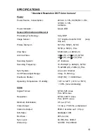
Page 21: ...V PAL Scanning System 2 1 Interlace Scanning Frequency 15 75KHz H x 60Hz V NTSC 15 625KHz H x 50Hz V PAL Sync System Line Lock Internal Vert Phase Adjust Range 0 deg To 360 deg Electronic Shutter 1 60 1 50 1 100000 sec Operating Temperature Humidity 14 F to 122 F 10 C to 50 C 96 non condensing Video Signal Format NTSC 525 Lines PAL 625 Lines Resolution NTSC 330TV Lines PAL 320TV Lines Minimum Illu...

Page 22: ... ON OFF Dip Switch White Balance ON OFF Dip Switch Auto Quick Indoor Outdoor Sync Internal Line Lock Dip Switch Vert Phase Adjust Adjustable POT DC Iris Level Adjust Adjustable POT Connector and Mechanical Video Output BNC Connector Power Input 3 pin Terminal Block AI DC Output 4 pin mini din jack Standard Connection Lens Mount C CS Selected through back focus Mounting Hole 1 4 UNC Top and Bottom ...

Page 23: ...5KHz H x 60Hz V NTSC 15 625KHz H x 50Hz V PAL Sync System Line Lock Internal Vert Phase Adjust Range 0 deg to 360 deg Electronic Shutter 1 60 1 50 1 100 000 sec Operating Temperature Humidity 14 F to 122 F 10 C to 50 C 96 non condensing Video Signal Format NTSC 525 Lines PAL 625 Lines Resolution NTSC 480 TV Lines PAL 470 TV Lines Minimum Illumination 0 8 Lux F1 2 Video Output 1 0 Vp p 75 Ohms unba...

Page 24: ...k Indoor Outdoor Sync Internal Line Lock Dip Switch Vert Phase Adjust Adjustable POT DC Iris Level Adjust Adjustable POT Connector and Mechanical Video Output BNC Connector Power Input 3 pin Terminal Block AI DC Output 4 pin mini din jack Standard Connection Lens Mount C CS Selected through back focus Mounting Hole 1 4 UNC Top and Bottom External Dimensions 2 4W x 2 1H x 5 0D inch 62W x 54H x 127D...

Reviews: