background image

Section V 

Battery Pack

006-0006504  02/27/18 


Rev R 

41 of 56 

UPS-3000 Guide 

www.synqor.com

Battery Capacity

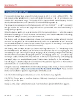
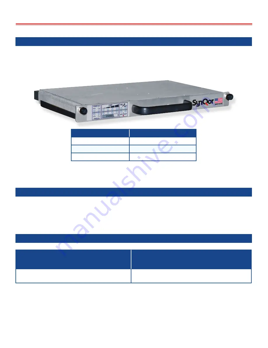
The SynQor UPS-3000-S supports the BAT-0200-S-1U-000 1U battery pack. It has approximately 

200 watt-hours of energy storage and a recharge time of <2 hours.  It has 3 battery segments and 

weighs 10.5 lbs.  Its run-time, as a function of UPS load power, is:

Total UPS Output Power

Standard Battery Run-Time

100% Rated Power

10 Minutes

80% Rated Power

13 Minutes

50% Rated Power

21 Minutes

The Standard battery pack fits into the 2U high UPS-3000S unit. Two battery packs are required for 

proper operation of the UPS-3000.

Storage of the Battery Pack

The storage temperature range of the battery pack (whether it is inserted in the UPS or stored 

separately) is -40

o

C to +65

o

C (-40

o

F to +150

o

F).  Care must be taken to ensure this range is not 

exceeded or the battery’s energy storage capacity and/or life may be degraded.

Battery Pack Replacement 

Battery Packs

3000S Series 

(2U; 65 lbs.)

2 battery packs required

Standard Battery Pack

BAT-0200-S-1U-000 

(200 Watt Hours)

Other options also available, check the website or contact [email protected] for further information.


Always use the proper SynQor battery pack.

Summary of Contents for UPS-3000-S-2U

Page 1: ...ninterruptible Power Supply 1 888 567 9596 USA only SynQor Headquarters 155 Swanson Road Boxborough MA 01719 1316 USA www synqor com Made in USA UPS 3000 S 2U N M Redundancy optional Operator s Guide...

Page 2: ...cy 13 Total Output Power that can be derived from the AC INPUT 14 Power Cable Wiring Diagram 17 Power Cable Wire Size 18 Section III Operation Set Up 19 Start Up 20 Shut Down 20 Power Cable Connection...

Page 3: ...arallel F option 39 Multi unit AC Output On Off Control Expanded Parallel R option 39 AC Output Neutral Grounding 39 Section V Battery Pack Battery Technology 40 Electronic Circuitry within the Batter...

Page 4: ...ce of AC power and not connected to the UPS do not contact the exposed terminals of the AC input cable Do not assume that the source of AC power is not present Connections between the AC input cable a...

Page 5: ...t apply external voltages to the pins of an exposed battery pack connector It is not possible to charge the battery pack from an external source and excess voltages could damage internal control circu...

Page 6: ...pdf Please contact the factory for all other questions regarding the UPS battery pack CAUTION Do not dispose of batteries in a fire The batteries may explode CAUTION Do not open or mutilate batteries...

Page 7: ...with a crest factor up to 2 5 and any load power factor from 0 0 to 1 0 There are two optional DC outputs at various voltage and power levels The total AC plus DC output power is limited to 2500 W Th...

Page 8: ...sources the AC INPUT the optional DC INPUT or the battery with that order of priority based on availability EMI filters are present at all external inputs and outputs AC INPUT DC INPUT DC2 OUTPUT 2x...

Page 9: ...ch cannot be used directly in parallel The DC2 option provides a single parallelable output up to 2500 W When the DC2 option is selected the DC Input is not available The DC1 and DC2 outputs are isola...

Page 10: ...power AC plus DC A 2U high 65 lbs rackmount unit that uses two standard battery packs which provide 10 minutes of battery run time at full power Each format has various options that can be specified...

Page 11: ...d Temperature 15 26 V at 0 A 22 V at 100 A 2200 W 28 V Option Voltage Regulation Over Load Temperature 13 30 V at 0 A 26 V at 96 2 A 2500 W Specifications subject to change without notice ENVIRONMENTA...

Page 12: ...CANNON 24 10 A D C B G E F B 5 15 1 6 11 1 6 11 10 5 15 10 OFF OFF O N O F F O N O F F ITT 22 2 A C B POWER OUT POWER IN LOAD CHARGE FAN BATT BATT UPS POWER OUT POWER IN LOAD CHARGE FAN BATT BATT UPS...

Page 13: ...he UPS 3000 series uninterruptible power supplies delivers power to its AC OUTPUT from a 230 Vrms AC INPUT an 115 Vrms AC INPUT or a 28 V DC INPUT 70 0 75 0 80 0 85 0 90 0 95 0 0 400 800 1200 1600 200...

Page 14: ...on on transient conditions 0 400 800 1200 1600 2000 2400 2800 25 30 35 40 45 50 55 Output Power Watts Air Temperature C UPS Output Power vs Air Temperature VAC IN 105VRMS or VDC IN 22V or power drawn...

Page 15: ...ween the curves shown For example the total output power that can be derived from the AC INPUT when the voltage is 97 5 Vrms would be 2500 W up to an ambient temperature of 50o C 122o F and then derat...

Page 16: ...ly while the AC output is loaded to 1500 W or greater the available DC1A and or DC1B output power is reduced as shown in Figure 4 In order to achieve the rated DC1 output power the AC output must be l...

Page 17: ...functions and locations AC INPUT Pin Function A Line B Neutral C Ground ITT 22 2 A C B DC INPUT Pin Function F E D Vin A B C Vin Return ITT CANNON 24 10 A D C B G E F AC OUTPUT Pin Function A Line B N...

Page 18: ...cables because the current flowing through it is very high as high as 124 A for the UPS 3000 Series and the voltage across it is already relatively small as low as 22 V In fact a common problem that...

Page 19: ...the correct polarity Connect the USER I O cables Connect all INPUT cables first to the UPS and then to the various sources An overcurrent protect and disconnect device should be installed on the DC IN...

Page 20: ...ng as the battery has charge left in it This is sometimes referred to as a COLD START in the industry Under this condition the LED above the ON OFF switch and the battery pack s LEDs will initially al...

Page 21: ...a load that might be connected to the other output NOTE that disconnecting an input or output power cable while that cable is handling power will likely cause an arc to form as the terminals are pulle...

Page 22: ...not otherwise maintain its specified maximum temperature for its internal circuitry the fans will be driven at a speed that exceeds their rated long term running speed There is an LED on the front pan...

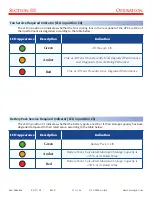
Page 23: ...Indication Green UPS is Running Outputs are Enabled Amber UPS is on Standby Outputs are Enabled Red UPS has a Fault Condition Off UPS is Off LEDs on the Battery Packs Each battery pack has 16 LEDs as...

Page 24: ...Source of Power Amber Input has Returned within Range and Diagnostic Tests are Being Performed Off Input is Not within Range Or the DC INPUT Option is not Installed Power Out Indicators LEDs in positi...

Page 25: ...reen B3 Off Total Load Power 75 B0 B1 B2 Green B3 Dimmed Green Total Load Power 100 B0 B1 B2 Green B3 Blinking Red Total Load Power 100 Battery State of Charge Indicators LEDs in positions E0 E3 The L...

Page 26: ...S Temperature Fans Running at 100 Red Maximum UPS Temperature Fans Running at 110 Battery Pack Temperature Indicator LED in position F1 The LED in position F1 indicates the temperature of the battery...

Page 27: ...Recently Had Degraded Performance and Diagnostic Tests are Being Performed Red One or All Fans Presently Have Degraded Performance Battery Pack Service Required Indicator LED in position C1 The LED i...

Page 28: ...Both Battery Packs and the Remaining Charge of at Least One Pack is 10 Hot Swapping the Battery Packs The battery packs can be removed from and reinserted into the UPS without disrupting the delivery...

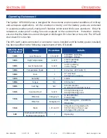
Page 29: ...acks installed has been qualified to the following requirements of MIL STD 810G MIL STD 810G Test Method Name Procedure Details 500 5 Low Pressure I II and III 18 000 ft operating 40 000 ft storage 50...

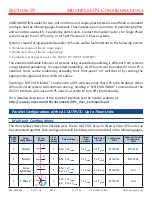
Page 30: ...ith redundant parallel units in multi unit systems Ordering Information Standard Vs Redundant Parallel AC Output Neutral Wire option Example PN Single Unit no paralleling G UPS 1500 S 1U W1GS00 ECE St...

Page 31: ...witch on or by sending the appropriate signal over the USER I O cable If any UPS unit is off all of the UPS units will disable their outputs If any UPS unit cannot deliver output power because it cann...

Page 32: ...USER I O cables Sending a OUTPUT DISABLE command to a UPS will cause only that UPS to be disabled Other UPS units in the system will continue running Sending a SYSTEM DISABLE command over the RS 232...

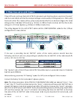
Page 33: ...phase systems redundant 3 phase systems or redundant single phase systems with more than three units Parallel Connection of the AC Outputs Two or three SynQor UPS units can have their AC OUTPUTs conne...

Page 34: ...redundant parallel the wiring diagram for the AC OUTPUT cables and the CONFIGURATION cable is shown below L1 N PEGND L1 N PEGND L1 N PEGND CONFIGURATION cable SYN 9315 or SYN 9343 AC OUTPUT AC OUTPUT...

Page 35: ...ally hot meaning at a high potential relative to the neutral or PEGND One will be phase shifted by 180 degrees one half cycle from the other meaning that when one hot wire is at its positive peak the...

Page 36: ...AC OUTPUT cable all the cable sections should have the following minimum wire size depending on whether the AC OUTPUT of the individual UPS units is 115 Vac or 230 Vac UPS AC Output Voltage Cable Mini...

Page 37: ...hat configuration cables for two unit and three unit single phase systems are offered as standard products See the previous pages for part numbers Line 1 UPS Unit 1 0 Line 2 UPS Unit 1 180 Line 1 UPS...

Page 38: ...ed to sources of power They could be connected to the same AC and or DC source respectively They could be connected to different AC and or DC sources respectively All that is necessary is to ensure th...

Page 39: ...e e g no AC or DC input and depleted battery the combined AC output will shutdown Multi unit AC Output On Off Control Expanded Parallel R option For expanded parallel multi unit operation any on front...

Page 40: ...s into multiple segments is to allow the battery pack to remain useful even if one of its battery cells fails In a normal battery configuration the failure of a single cell would disable the entire ba...

Page 41: ...battery pack fits into the 2U high UPS 3000S unit Two battery packs are required for proper operation of the UPS 3000 Storage of the Battery Pack The storage temperature range of the battery pack whe...

Page 42: ...this chassis and the exposed power terminal strip is not subjected to extreme mechanical shock or to excessive moisture UPS battery packs must be shipped per Federal DOT Regulations as a Class 9 Full...

Page 43: ...optional connection to a host system computer so that it can control the UPS and receive information regarding the status of the UPS The Configuration male DB15 connector on the right is for a connect...

Page 44: ...8 2N3904 Input Pin 50k Ohms 100 Ohms 5V 500 Ohms PS2581L 1N4148 I O Circuits OUTPUT ON OUTPUT OFF 5V Pin SHUTDOWN Input Pin Remote On Off Switch SPDT Momentary ON OFF ON 100 Ohms 5V 8 500 Ohms 13 PS25...

Page 45: ...ollector output where low indicates the UPS is drawing power from its battery OUT_OK 14 Open collector output where low indicates AC Output voltage is within range OVER_TEMP 15 Open collector output w...

Page 46: ...carriage returns with line feeds and use local echo UPS 3000 S 2U with DC Input DC1 Output Options Exhaust Fans DC1 Output Option AC Output Ethernet Port Option User I O CONFIG Port Ground Stud 1 4 2...

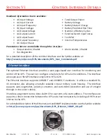
Page 47: ...pdf Ethernet Interface The optional Ethernet interface provides a web page based user interface for monitoring and control of the UPS The user can configure email alerts for UPS alarm conditions The i...

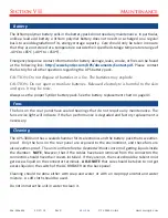
Page 48: ...n and eyes It may be toxic Always use the proper SynQor battery pack See the battery replacement chart on page 41 Fans The fans on the rear panel have sealed bearings that do not require any maintenan...

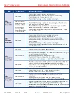
Page 49: ...ed by the user The 16 LEDs on the front panel of the battery pack are the best and first place to look to determine what might be wrong with the UPS The table on the next several pages is therefore or...

Page 50: ...oltage is either too low or too high The DC INPUT cable may have too much series resistance Thicker wire should be used A1 AC OUTPUT Power LED LED is OFF The UPS is OFF and needs to be turned ON LED i...

Page 51: ...o keep the unit cool The maximum recommended temperature may be exceeded but the fans are keeping things cool enough to avoid triggering the over temperature shut down circuitry F1 Battery Pack Temper...

Page 52: ...The UPS s battery run time will therefore be similarly reduced The battery pack should be replaced at the earliest convenient time All 16 LEDs All LEDs are OFF The battery pack is not fully inserted i...

Page 53: ...ted to the UPS Or it may happen when the load itself is turned on and or connected to the AC OUTPUT of a UPS that is already running Common examples of such loads are motors and incandescent lights bu...

Page 54: ...drop from the upstream to the downstream end of the cable This voltage drop if large enough will cause the either UPS to determine that the voltage at its AC INPUT or its DC INPUT is below its minimum...

Page 55: ...s trying to draw power from the DC INPUT for one minute After this one minute another set of 3 cycles are repeated followed by another stop for one minute and so on This same problem can also occur fo...

Page 56: ...rade Uninterruptible Power Supply 006 0006504 02 27 18 Rev R 1 888 567 9596 USA only SynQor Headquarters 155 Swanson Road Boxborough MA 01719 1316 USA www synqor com Made in USA Operator s Guide UPS 3...

Reviews: