Synergy Global Technology LCDR9U19-02 User Manual Download Page 17


*1. In order to control the device to operate in Zoom mode, the computer has to 

fi

 rst send    


     command code ” to switch the signal source from camera to VCR/DVR, at this time the device will  


     automatically zoom channel 1 video from VCR/DVR to full screen. User can then input a correspond- 


     ing channel code to zoom any other speci

fi

 c channel. Input the corresponding channel code again to  


     put the speci

fi

 c channel to freeze mode and send the code again to clear the freeze mode.


     Example: Input GE, (GE) B, (GE) C, and (GE) D for zooming the video signal in channel 1 to 4 from  


     VCR/DVR. Input “A”, “B”, “C”, “D” again to freeze the speci

fi

 c channel. Send command code “G”    


     again to get back to Live input mode.


*2. Computer has to send out command code “H” continuously for 2 seconds to switch the device be- 


      tween security lock ON and OFF mode. If any alarm is activated under security lock ON mode, the  


      device has to send out command code “H” continuously for more than 4 seconds to clear the alarm.


*3. Setup menu is switched ON by sending VCR/DVR and Lock button codes together. 


*4. Text Select and Cursor Control functions can be performed only under menu Setup mode.

 2.2


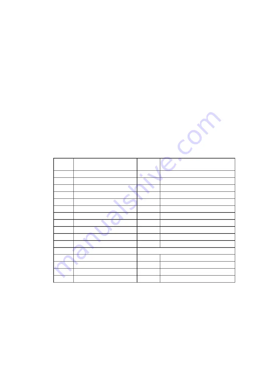
Right after computer/terminal has sent out the above mentioned control command code to the device, the


       device will respond with following status code back to computer through RS-232 port:

Status 

Code

Quad Status

Status 

Code

Quad Status

EF

Device in Quad mode

DE

CH1 in Sequence mode

EE

CH1 in Freeze mode

DD

CH2 in Sequence mode

ED

CH2 in Freeze mode

DB

CH3 in Sequence mode

EC

CH1 & 2 in Freeze mode

D7

CH4 in Sequence mode

EB

CH3 in Freeze mode

CF

Quad display in Sequence mode

EA

CH1 & 3 in Freeze mode

E9

CH2 & 3 in Freeze mode

E

CH1 in Full screen mode

E8

CH1, 2, & 3 in Freeze mode

D

CH2 in Full screen mode

E7

CH4 in Freeze mode

B

CH3 in Full screen mode

E6

CH1 & 4 in Freeze mode

7

CH4 in Full screen mode

E5

CH2 & 4 in Freeze mode

E4

CH1, 2 & 4 in Freeze mode

Attach to above code

E3

CH3 & 4 in Freeze mode

XX-DF

Buzzer/VCR ON

E2

CH1, 3, & 4 in Freeze mode

XX-7F

Security lock ON

E1

CH2, 3, & 4 in Freeze mode

XX-3F

Buzzer & Security lock ON (Stop)

E0

CH1, 2,3, & 4 in Freeze mode

< 4.3 > QD  Remote Control Connection & Operation 

P.13

www.rackmountmart.com

Summary of Contents for LCDR9U19-02

Page 1: ...Toll Free 1 888 865 6888 Tel 510 226 8368 Fax 510 226 8968 Email sales RackmountMart com...

Page 2: ...User Manual 9U Quad Display LCDR9U19 0 2 19 LCD Options DC power...

Page 3: ...sis Opening it yourself could damage the equipment and invalidate its warranty If any part of the equipment becomes damaged or stops functioning have it checked by qualified service personnel What the...

Page 4: ...Package Content 1 2 Structure Diagram Dimension 1 3 Installation Contents P 1 P 1 2 P 3 Contents Quad Display Connection Operation 4 1 QD Connection 4 2 QD ALARM Connection Operation 4 3 QD Remote Co...

Page 5: ...U19 0 2 unit X 1 6ft VGA cable X 1 Power adapter X 1 Power cord X 1 1 2 Structure Diagram 1 Front view Rear view 4 Power adapter Power cord 3 LCD panel LCD OSD membrane Quad display control membrane P...

Page 6: ...ension P 2 Front View Side View UNIT mm 1mm 0 03937 inch Bottom View Model Product Dimension W x D x H Net Weight LCDR9U19 0 2 480 x 68 5 x 399 mm 18 9 x 2 7 x 15 7 inch 9 5 kg 20 9 lbs www rackmountm...

Page 7: ...Setu p VCR SEQ Qu ad Dis pla y Co ntr ol LC D OS D Me nu 1 3 Installation Step Mount the display panel with M6 screw set M6 screw x 8 pcs required Left right side M6 screw sets are not provided 1 Ste...

Page 8: ...90 non condensing Storage Temperature 5 to 60 C degree Humidity 5 90 non condensing Shock 10G acceleration 11ms duration Vibration 5 500Hz 1G RMS random LCD Panel Manufacturer Panel Size diagonal 19 i...

Page 9: ...75Hz 1152 x 864 x 75Hz 1024 x 768 x 60 70 75Hz 848 x 480 x 60Hz 800 x 600 x 60 72 75Hz 720 x 400 x 70Hz 640 x 480 x 60 72 75Hz 640 x 400 x 70Hz 640 x 350 x 70Hz Physical Specification Product W x D x...

Page 10: ...Power on off LCD Power light Green On Orange Power saving Membrane Switch Function OSD Configuration Page Image for the brightness contrast color temp red green and blue Geometry for the auto adjust H...

Page 11: ...2 Volt 24 Volt 48 Volt Input range 9 18V 18 36V 36 75V Input current No load 50 mA 50 mA 50 mA Full load 4950 mA 2450 mA 1220 mA Output rating Output voltage 12 Volt 12 Volt 12 Volt Output current 4 1...

Page 12: ...ncorrect termination will degrade the quality of the video signal All video inputs not looped through to another device the corresponding switches need to be set to 75 termination position If another...

Page 13: ...to record for longer period of time Combined with alarm sensor detection the VCR will record only when an alarm sensor is activated If more than one sensor have been trigged VCR will start to record...

Page 14: ...In contact pin 5 of the female type 9 pin D sub connector 8 to GND 2 The Alarm Duration time elapses 3 If the device is operated under Security Lock ON mode Push Lock button for 2 seconds to disable t...

Page 15: ...h i z 1 2 3 4 75 IN OUT RS 232 ALARM dc 12V 1amp monitor vcr I O RS 232 Cable Wire Computer Remote Keypad Rear Panel 4 3 QD Remote Control Connection Operation P 11 www rackmountmart com...

Page 16: ...ed to the male type 9 pin D sub connector on the real panel from it RS 232 port to control this device using standard uppercase ASCII codes 2 1 The ASCII command codes for the quad are listed in the t...

Page 17: ...hed ON by sending VCR DVR and Lock button codes together 4 Text Select and Cursor Control functions can be performed only under menu Setup mode 2 2 Right after computer terminal has sent out the above...

Page 18: ...larm operations of the unit BYTE 1 Status code for normal operation modes Channel Select 1110 CH1 1101 CH2 1011 CH3 0111 CH4 Display Mode 0 Quad screen display 1 Full Screen display Auto sequencing mo...

Page 19: ...or alarm operations The first 4 bits show the sensor activated alarm status of each channel next 4 bits show the video loss alarm status of each channel The digit 1 means alarm event is detected and 0...

Page 20: ...ese two buttons simultaneously to get into Menu Setup mode and display page 1 of system setup menu Push these two buttons simultaneously again to display page 2 of the setup menu Use page 1 to program...

Page 21: ...ach video channel The available alphanumeric characters are 0 1 2 3 4 5 6 7 8 9 A B C D X Y Z space 1 2 DWELL Time setup The Dwell time menu permits setting the dwell time for all cameras and the Quad...

Page 22: ...ensor a blinking message will display In this case the buzzer will be activated when you exit the setup operation 2 2 Alarm Sensitivity Alarm sensitivity can be programmed to different extent by setti...

Page 23: ...first turn the quad display button 4 to ON to set the unit to display in the quad mode At this time you may press any of the four channel selection buttons 5 to freeze the corresponding channel 7 2 Un...

Page 24: ...or 16 7 M 16 7 M Imaging System NTSC PAL Resolution 1024 x 525 1024 x 625 Refresh Rate 60 50 Video Input Camera Input 1 0 Vpp 75 Ohm x 4 VCR Input 1 0 Vpp 75 Ohm x 1 Video Output Live Monitor 1 0 Vpp...

Page 25: ...prior notice and assumes no responsibility for any error which may appear in this publication All brand names logo and registered trademarks are properties of their respective owners Copyright 2012 S...

Reviews: