Synergy Global Technology ID-H17A User Manual Download Page 37

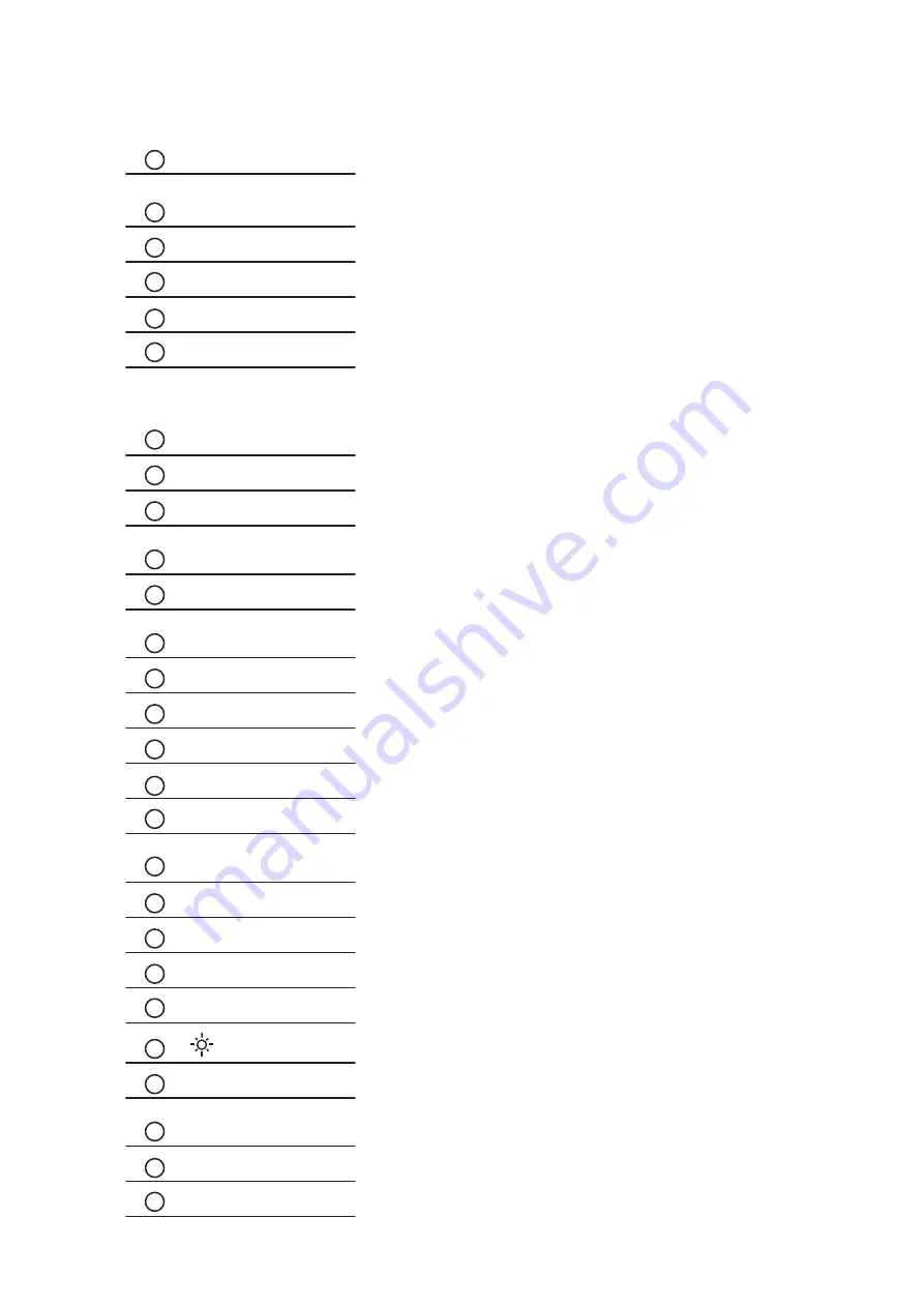
14.1   Remote Controller Options           


Chapter 14

P.33

POWER

Switches on or off the TV

1 - 9

Only use in TV mode. Select channels. For channel numbers 10 and 
above, enter the second digit within two seconds.

DISPLAY

Press this button will show the current input source

SELECT

Select the input source

ENTER

Enter to the select item settings or excude the setting

MENU

Display the menu on the screen or go to the previous menu

 / 

 / 

 / 

Go to the upper menu or select the previous value /
Go to the next menu or select the next value / 
Decrease the setting value / 
Increase the setting value or enter to the select item setting

CH + / -

Increase or decrease the channel number

FREEZE

Freeze the main channel display picture

AUDIO

Select sound effect: NORMAL, POPULARITY, ROCK, JAZZ, CLAS-
SICALLY, USER

ADJUST

Only used in VGA mode. Adjust the screen position

ASPECT

Set the main display aspect ratio mode: FULL SCREEN, PILLAR 
BOX

SOURCE

Only used in PIP mode. Select PIP input source

PIP

Turn on or off the PIP Channel

SLEEP

Select the sleeping time

MUTE

Turn on or off the speaker

INPUT

Select the Main Channel input source

CLEAR

Press this button will hide the current input source name on the Top-
Left position

BACK

Return to the previous channel watched

EXIT

Exit the menu or cancel

VOL + / -

Increase or decrease the speaker volume

ZOOM + / -

Zoom in or out the screen 


+ / -

Increase or decrease the brightness

SWAP

Swap the input source with Main Channel and PIP Channel

POSITION

Set the position of the PIP screen: BOTTOM-LEFT, BOTTOM-RIGHT, 
TOP-LEFT, TOP-RIGHT

PIP AUDIO

Alternate the main screen speaker or PIP screen speaker

PIP ASPECT

Set the PIP display aspect ratio mode: FULL SCREEN, PILLAR BOX

1

8

2

3

4

5

6

7

9

10

11

12

13

14

15

16

17

18

19

20

21

22

23

24

25

26

27

ID-H17A/H17AN/H17D/H17P

Summary of Contents for ID-H17A

Page 1: ...Toll Free 1 888 865 6888 Tel 510 226 8368 Fax 510 226 8968 Email sales RackmountMart com...

Page 2: ...ID H17A Front aluminum LCD panel ID H17D Stylish front aluminum cover LCD panel ID H17AN Front NEMA4 IP 65 LCD panel User Manual 17 SunReadable LCD Options AV BNC DVI Touchscreen DC power TV tuner Au...

Page 3: ...6 7 Chapter 3 ID H17AN SunReadable front NEMA4 IP 65 LCD panel 3 1 Package Contents 8 3 2 Structure Diagram 9 3 3 Dimension Diagram 10 3 4 Mounting Method 11 12 Chapter 4 ID H17D SunReadable stylish f...

Page 4: ...Option 24 9 4 On screen Menu for DVI BNC S Video RCA Input 25 26 Chapter 10 Touchscreen Options 10 1 Touchscreen Quick User Guidelines 27 28 Chapter 11 DC Power Options 29 Chapter 12 TV Tuner Options...

Page 5: ...htning or other acts of nature unauthorized product modifi cation or failure to follow instructions supplied with the product Repair or attempted repair by anyone not authorized by us Any damage of th...

Page 6: ...ce for connecting the LCD Display to the related facilities should be well considers too The LCD Display comes with the standard parts shown on the package contents Check and make sure they are in clu...

Page 7: ...x 1 pc Power cord x 1 pc Auto switch power adapter x 1 pc Mounting bracket A x 4 pcs Mounting bracket B x 12 pcs M4 6mm screw x 8 pcs M4 50mm screw x 12 pcs 5 4 2 1 3 User Manual 1 5 4 3 2 7 9 6 8 8 6...

Page 8: ...2 2 ID H17A series Structure Diagram Chapter 2 5 1 2 3 Front View Rear View 4 Rear case Class A TFT LCD panel 4mm protective glass 1 2 6mm aluminum front bezel LCD membrane 4 5 3 ID H17A H17AN H17D H...

Page 9: ...2 3 ID H17A series Dimension Diagram Chapter 2 Front View Rear View P 5 UNIT mm 1mm 0 03937 inch ID H17A H17AN H17D H17P...

Page 10: ...7A series Mounting Method Chapter 2 1 4 3 2 Mounting bracket A x 4 pcs x 12 pcs x 8 pcs x 12 pcs Mounting bracket B P 6 M4 6mm screw M4 50mm screw Mounting bracket A Mounting bracket B ID H17A H17AN H...

Page 11: ...pcs for VESA mounting is not provided To avoid damage of internal components when mounting the VESA bracket do not use screws that exceed the depth 6mm of the display mounting holes Using screws that...

Page 12: ...lease refer to p 11 12 LCD display x 1 pc 6 VGA cable male to male x 1 pc User manual x 1 pc Power cord x 1 pc Auto switch power adapter x 1 pc Mounting bracket A x 4 pcs Mounting bracket B x 12 pcs M...

Page 13: ...eries Structure Diagram Chapter 3 5 1 2 3 Front View Rear View 4 Rear case Class A TFT LCD panel 4mm protective glass Front NEMA 4 IP65 protection 1 2 6mm aluminum front bezel LCD membrane 4 5 3 ID H1...

Page 14: ...3 3 ID H17AN series Dimension Diagram Chapter 3 P 10 Front View Rear View UNIT mm 1mm 0 03937 inch ID H17A H17AN H17D H17P...

Page 15: ...AN series Mounting Method Chapter 3 P 11 1 4 3 2 Mounting bracket A x 4 pcs x 12 pcs x 8 pcs x 12 pcs Mounting bracket B M4 6mm screw M4 50mm screw Mounting bracket A Mounting bracket B ID H17A H17AN...

Page 16: ...pcs for VESA mounting is not provided To avoid damage of internal components when mounting the VESA bracket do not use screws that exceed the depth 6mm of the display mounting holes Using screws that...

Page 17: ...ries Package Contents Chapter 4 P 13 LCD display x 1 pc 6 VGA cable male to male x 1 pc User manual x 1 pc Power cord x 1 pc Auto switch power adapter x 1 pc 5 4 2 1 3 User Manual 1 5 4 3 2 ID H17A H1...

Page 18: ...5 4 2 ID H17D series Structure Diagram Chapter 4 1 2 3 Front View Rear View 4 Rear case Class A TFT LCD panel 4mm protective glass 1 2 1 2mm front aluminum cover LCD membrane 4 5 3 ID H17A H17AN H17D...

Page 19: ...4 3 ID H17D series Dimension Diagram Chapter 4 Front View Rear View P 15 UNIT mm 1mm 0 03937 inch ID H17A H17AN H17D H17P...

Page 20: ...pcs for VESA mounting is not provided To avoid damage of internal components when mounting the VESA bracket do not use screws that exceed the depth 6mm of the display mounting holes Using screws that...

Page 21: ...ries Package Contents Chapter 5 P 17 LCD display x 1 pc 6 VGA cable male to male x 1 pc User manual x 1 pc Power cord x 1 pc Auto switch power adapter x 1 pc 5 4 2 1 3 User Manual 1 5 4 3 2 ID H17A H1...

Page 22: ...P 18 5 2 ID H17P series Structure Diagram Chapter 5 4 1 2 Front View Rear View Rear case Class A TFT LCD panel 1 2 Universal open frame mounting LCD membrane 3 3 4 ID H17A H17AN H17D H17P...

Page 23: ...5 3 ID H17P series Dimension Diagram Chapter 5 Front View Rear View P 19 UNIT mm 1mm 0 03937 inch ID H17A H17AN H17D H17P...

Page 24: ...100mm VESA standard Remarks Hardware and M4 4 pcs for VESA mounting is not provided To avoid damage of internal components when mounting the VESA bracket do not use screws that exceed the depth 6mm of...

Page 25: ...vices before connecting them Apply power to connected devices again only after the LCD Display re ceiving power The company is not responsible for damage caused in this way Power 7 1 On screen Display...

Page 26: ...ter into the phase clock sub menu H V POSITION H V Position Align the screen image left or right and up or down MISC Information Display the current resolution refresh rate and frequency information o...

Page 27: ...ng 100 to 240VAC 50 60Hz Power Consumption Max 40 Watt Standby 5 Watt Compatibility Multi platform Mix PCs SUNs IBMs HPs DELLs Options Graphic Input DVI D BNC S Video RCA video input DC Power DC power...

Page 28: ...a 6 DVI D cable 9 2 S Video RCA Input Option Remarks Package includes an extra 6ft S Video and 6ft RCA cables VGA Power S Video VGA Power 9 3 S Video BNC Input Option Remarks Package includes an extra...

Page 29: ...eft or right V Position Align the screen image up or down Clock Adjust the clock value Phase Adjust the phase value 3 Function OSD Position Adjust OSD menu horizontal and vertical position OSD Zoom Ad...

Page 30: ...ess Saturation X X Hue X X Geometry Auto Config N A N A N A H Position N A N A N A V Position N A N A N A Clock N A N A N A Phase N A N A N A Function OSD Position OSD Zoom Color Temp System Language...

Page 31: ...CD disc As the touchscreen unit is not made of toughened glass please handle it carefully USB VGA Power Serial VGA Power USB interface Serial interface Model 17TRB 17TRS Screen size 17 Interface USB...

Page 32: ...he record will bcome default record Press 25ptCal to do 25 points calibration Correct 25 point locations on screen with the panel Touch the blinking symbol on panel until beep or stop blinking After t...

Page 33: ...ut range 9 18V 18 36V 36 75V Input current No load 50 mA 50 mA 50 mA Full load 4950 mA 2450 mA 1220 mA Output rating Output voltage 12 Volt 12 Volt 12 Volt Output current 4 16A 4 16A 4 16A Efficiency...

Page 34: ...2 1 TV Tuner Options Chapter 12 12 2 How to Use Remote Controller How to use remote controller please refer to p 32 33 1 2 3 4 5 TV Audio out Audio in Audio L 1 Audio R Video S Video DVI 4 2 3 5 6 7 8...

Page 35: ...P 31 13 1 Audio Input Options Chapter 13 1 2 3 4 5 Audio in Audio L Audio R 1 VGA Power 4 2 3 5 ID H17A H17AN H17D H17P...

Page 36: ...7 9 10 11 12 13 14 15 16 17 18 20 25 24 23 22 19 21 26 27 AUDI O ASPECT PIP SLEEP FREEZE ADJUST SOURCE SWAP PIP AUDI O POSITION PIP ASPECT ZOOM ENTER CH POWER 1 DISPLAY 7 4 CLEA R INPUT 3 9 6 MUTE 2 8...

Page 37: ...nly used in VGA mode Adjust the screen position ASPECT Set the main display aspect ratio mode FULL SCREEN PILLAR BOX SOURCE Only used in PIP mode Select PIP input source PIP Turn on or off the PIP Cha...

Page 38: ...red or sized properly Press the button for two seconds to automatically adjust the image Adjust the H position and V position settings via On screen menu 5 Must calibration be down after installation...

Page 39: ...ay or pour any liquid onto the screen directly 3 To remove dust and other particles wipe the screen with a clean soft lint free cloth 4 Be cautions of all kinds of cleaning solvents or chemicals some...

Reviews: