

DOC-1000544-A-
1
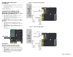
POWERING THE DIM10-087-06
CONTROLLER
3.
Connect the 5-24VDC Aux output from LED driver
to the DIM10-087-06.
4.
Connect the Aux ground from the LED driver to the
DIM10-087-06
.
(Figure 2 and Figure 3)
CONNECTING THE DIMMING CIRCUIT
Note: Steps 5-6 are for connecting up to a
Standard Dim to Off LED driver; if you are using a
DALI 2 LED driver skip to steps 7-8.
5.
Connect the DIM- wire on the LED driver to the
DIM- output on the DIM10-087-06.
6.
Connect the DIM+ wire on the LED driver to the
DIM+ output on the DIM10-087-06.
(See Figure 2)
Note: Steps 7-8 are for connecting up to a DALI 2
LED driver.
7.
Connect both the DALI– and DIM– from the
DIM10-087-06 to the COMMON/DALI- wire on the
LED driver.
8.
Connect the DALI+ from the DIM10-087-06 to the
LED driver DALI+. Figure 3 – DALI 2 Wiring
Diagram
(See Figure 3)
STATUS LED
Note: When the controller is powered the
following colors indicate the current status.
•
Red
= No Network Found (Communication Lost)
•
Blinking Green
= Network Found, Controller Not
Configured (Device not yet added to
SimplySNAP)
•
Green
= Network Found, Controller Configured
(Normal Operation)
Figure 2 – Dim to OFF Wiring Diagram
Figure 3 – DALI-2 Wiring Diagram
STATUS LED