


26
TimeProvider 500 2.0 User’s Guide
098-00172-000 Revision A – December, 2009
Chapter 1 Overview
Functional Description
Functional Description
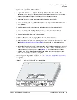
is a front view of the TimeProvider 500. All user connections are on the
front panel.
Figure 1-4.
TimeProvider 500 Front Panel
PowerA and PowerB Connectors
Molex-style connectors are used to provide –48 VDC (labeled
POWERA
and
POWERB
). When the unit is successfully powered, the PWR LED near the left-side
of this panel illuminates green. If the power connection is reversed, the unit will not
be damaged, it simply will not power-up. Startup power will be less than 9.2 watts.
Steady-state power (at a nominal temperature of 25° C) is less than 5.3 watts.
The TimeProvider 500 uses –48 VDC power and is not equipped with a power
switch. Power to the unit must be controlled by a Branch Circuit Over-Current
Protection Device to the DC power main.
Warning:
To avoid serious personal injury or death, exercise caution
when working near high voltage lines and follow local building
electrical codes for grounding the shelf.
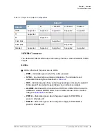
LEDs
-48 DC
Power
Connector A
10MHz
Connector
RS232
Serial
Port
Chassis
Ground
Link & Flow
LED
IEEE - 1588
&
Remote
Managment
-48 DC
Power
Connector B
1PPS/E1/T1
Outputs
E1/T1
Outputs
Summary of Contents for TimeProvider 500
Page 10: ...Table of Contents 10 TimeProvider 500 2 0 User s Guide 098 00172 000 Revision A December 2009 ...
Page 12: ...List of Figures 12 TimeProvider 500 2 0 User s Guide 098 00172 000 Revision A December 2009 ...
Page 146: ...146 TimeProvider 500 2 0 User s Guide 098 00172 000 Revision A December 2009 T1 Format ...
Page 174: ...Index W W 174 TimeProvider 500 2 0 User s Guide 098 00172 000 Revision A December 2009 ...