background image

PN 8500-0150, Rev. A, May 2005

17

Operating Manual

Operation

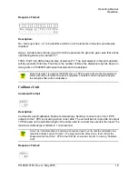
r - Revision Letter of Firmware. 

Response Format: 

Enter Start-up Parameters 

Command Format: 

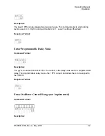
Description:

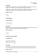
n - Start-up Index; n (1 to 6) selects which one of 6 elements in the start-up table that will be 
modified.

gg.g - Dynamic Gain Value; gg.g (0 to 99.9) represents the dynamic gain value that will be 
used during start-up for element "n".

tttttt - End Time; tttttt is the end time of element "n" (based on Rubidium lock). The next 
element in the start-up table will be used after this time.

Response Format:

Request Start-up Parameters 

Command Format: 

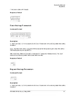
Description:

n - Start-up Index; n (1 to 6) selects which one of 6 elements in the start-up table that will be 
reported.

Summary of Contents for 5401

Page 1: ...5401 Airborne Disciplined Rubidium Oscillator 5402 Disciplined Rubidium Oscillator Operating Manual Preliminary Rev A May 2005 PN 8500 0150 ...

Page 2: ...of the copy Additional copies are also available from Symmetricom for a nominal fee In no case however does the supply of this manual or the granting of rights to reproduce the manual grant any rights to use information contained within to reproduce the supplied equipment or software either in whole or in part The equipment or software described in this manual have been developed solely at the exp...

Page 3: ...e Limited Warranty set forth above Symmetricom makes no other warranties express or implied of merchantability fitness for purpose or of any other kind or description whatsoever By purchasing any product manufactured by Symmetricom the buyer consents to and agrees with Symmetricom that as a result of the exclusion of all warranties expressed or implied of merchantability fitness for purpose or oth...

Page 4: ...ich it is purchased or loaned Where to Find Answers to Product and Document Questions For additional information about the products described in this guide please contact your Symmetricom representative or your local sales office You can also contact us on the web at www symmetricom com Warnings Cautions Recommendations and Notes Warnings Cautions Recommendations and Notes attract attention to ess...

Page 5: ...static discharge damage to or destruction of static sensitive components of the equip ment Electrical Shock Caution To avoid electrical shock and possible personal injury do not disregard electrical shock cautions All electrical shock cautions use this symbol Electri cal shock cautions are practices procedures or statements that if not strictly observed may result in possible personal injury elect...

Page 6: ...me is shown as it appears on the keyboard An explanation of the key s acronym or function immediately fol lows the first reference to the key if required SSU Username Text in a source file or a system prompt or other text that appears on a screen PING STATUS A command you enter at a system prompt or text you enter in response to a program prompt You must enter commands for case sensitive operating...

Page 7: ...m 5402 Disciplined Rubidium Oscillator 2 2 Installation Installation 3 Unpacking and Inspection 3 Symmetricom 5401 Installation Procedure 3 Symmetricom 5401 Initial Operation 3 Symmetricom 5401 Adjustments 4 Symmetricom 5402 Rack Mounting Procedure 5 Symmetricom 5402 Installation Procedure 6 Symmetricom 5402 Initial Operation 6 Symmetricom 5402 Adjustments 6 3 Operation RS 232 Input Output 7 Statu...

Page 8: ...ut Threshold High Low 21 Enter Programmable Delay Value 22 Enter Oscillator Control Range not implemented 22 Design Verify On Off 23 Cal Status 24 Enter Estimation Filter Time Constant 24 Enter Dynamic Gain Factors 25 4 Specifications Input Specifications and Characteristics 26 Output Specifications and Characteristics 27 5401 Indicators Front Panel 29 5402 Indicators Front Panel 29 DRO Internal T...

Page 9: ... assembly along with the necessary Power Supply Buffers and Distribution Amplifiers The High Resolution Disciplining assembly contains the logic to discipline the Rubidium oscillator to an external 1 PPS input This assembly also contains a 10 MHz oven oscillator that is phase locked to the Rubidium This provides a source for low noise 10 MHz sine wave outputs Two 3 Channel Distribution Amplifiers ...

Page 10: ...assis on a flat base plate Refer to Chapter 4 for complete specifications Figure 1 Symmetricom 5401 3 View Symmetricom 5402 Disciplined Rubidium Oscillator The Symmetricom 5402 is built in a standard rack mount configuration that is powered by commercial power anywhere in the world 85 to 264 VAC The unit is designed to be installed in a standard 19 inch RETMA electronic enclosure Chassis slides ar...

Page 11: ...S input to its 1 PPS source and connect the 1 PPS and 10 MHz outputs to their desired destinations Connection to the RS 232 I O is not necessary for operation but it is desirable in order to monitor status or enter new control parameters Symmetricom 5401 Initial Operation Upon completion of the installation 1 Apply power to the unit and observe that the green POWER LED indicator illuminates Note t...

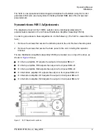
Page 12: ...1 Remove the screws that secure the left side panel to the unit Remove the side panel 2 Remove the screws that secure the back panel to the unit including the capacitor bracket The two Distribution Amplifiers Assembly 35039 are located one on top of the other as shown in Figure 3 below On the top amplifier R1 adjusts the output on front panel SMA J7 On the top amplifier R18 adjusts the output on f...

Page 13: ...erature of the rack environment may be greater than room ambient Therefore consideration should be given to installing the equipment in an environment compatible with the maximum rated ambient temperature TMRA Reduced Air Flow The equipment has no cooling fans and depends on convection for cooling Installation in a rack may cause an excessive heat rise if sufficient air flow is not available Insta...

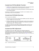
Page 14: ...t the green POWER LED indicator illuminates 2 After approximately five minutes the internal Rubidium oscillator will have attained lock resonance The 10 MHz outputs are now stable for use Disciplining of the Rubidium oscillator will begin once 1 PPS input is present The 5402 is now operational and will begin to discipline the Rubidium using the control parameters that were previously stored in bat...

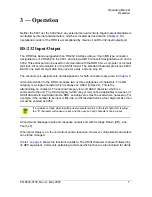
Page 15: ... to the DRO comprises two or three categories of characters The first category is a single character which is always an ASCII Hex 24 This is the attention log on character The second category is an ID ASCII character which is a command to the unit The third category which may or may not be applicable is a series of ASCII data bits to input data into the DRO Leading zeros must be used where necessa...

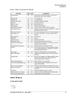
Page 16: ...Operating Manual Operation PN 8500 0150 Rev A May 2005 8 Table 1 DRO Commands Via RS 232 Status Request Command Format ...

Page 17: ...PS event Sssssss s Seconds Counter ssssss s is the second count 0 to 999999 9 seconds since the unit has been turned on The count will roll over to zero when maximum is reached Eddddd DAC value ddddd is the DAC value 0 to 65535 and is proportional to the voltage applied to the oscillator Hhhh h Temperature count hhh h is the dithered temperature sensor value Ggg g Dynamic Gain gg g is the current ...

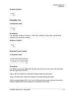
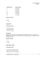
Page 18: ...at Dynamic Gain Control Command Format Description The dynamic gain value determines the response time of the control loop This command sets the upper and lower limit Fgg g Dynamic Gain Floor the lowest value allowed for dynamic gain Cgg g Dynamic Gain Ceiling the highest value allowed for dynamic gain With the default values for Km Ko1 Ko2 and Disgain the dynamic gain will produce the following a...

Page 19: ...er for Km kkkkkk 000000 to 999999 represents a number from 0 to 0 999999 Km controls the mix ratio of offset error and frequency error compensation in the discipline algorithm Response Format Enter KO1 KO2 Command Format Dynamic Gain Time Constant 4 90 minutes 5 70 minutes 8 45 minutes 10 35 minutes 20 17 minutes 30 11 minutes ...

Page 20: ...s the cut off frequency of the frequency error noise filter Response Format Enter Disgain Command Format Description ddddd Base number for Disgain ddddd 00000 to 99999 controls gain common to both the offset error and the frequency error paths of the discipline loop Response Format Enter Resync Threshold Command format Description rrrrrr rrr Resync Threshold rrrrrr rrr microseconds is the limit va...

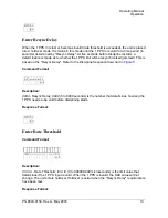
Page 21: ... jammed This is based on the Resync Delay Refer to the Discipline Sequence flowchart in Figure 5 Command Format Description dddd Resync Delay dddd 5 to 9999 seconds is the number that determines how long the 1 PPS needs to be valid before disciplining starts Response Format Enter Rate Threshold Command Format Description rrrrrr rrr Rate Threshold rrrrrr rrr 0 to 999999 999 microseconds is the limi...

Page 22: ...Rev A May 2005 14 Burst Status On Command Format Description Status will be output every second Response Format Burst Status Off Command Format Description Turns burst status off Response Format No Response When burst is on When burst is off ...

Page 23: ...PN 8500 0150 Rev A May 2005 15 Operating Manual Operation Figure 5 DRO Discipline Sequence Flowchart Request TI Command Format ...

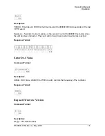
Page 24: ... s Seconds Counter ssssss s is the second count 0 to 999999 9 seconds since the unit has been turned on The count will roll over to zero when maximum is reached Response Format Enter DAC Value Command Format Description ddddd DAC Value ddddd 0 to 65535 counts controls the frequency of the oscillator Response Format Request Firmware Version Command Format Description DTyyy Firmware Number ...

Page 25: ...be modified gg g Dynamic Gain Value gg g 0 to 99 9 represents the dynamic gain value that will be used during start up for element n tttttt End Time tttttt is the end time of element n based on Rubidium lock The next element in the start up table will be used after this time Response Format Request Start up Parameters Command Format Description n Start up Index n 1 to 6 selects which one of 6 elem...

Page 26: ...mmands a self calibration Before commanding a Self Cal connect one of the 1 PPS outputs to the 1 PPS input using a short coax cable The unit will be set to provide an output 1 PPS based on the electrical length of the cable used to connect the output to the input The maximum cable delay is limited to 1 microsecond Response Format Note If element 1 is used not 000000 then a 1 PPS resync will occur ...

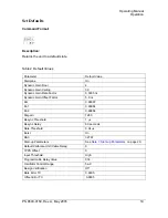
Page 27: ... Rate Factor 0 0005 ns Dynamic Gain Offset Factor 5 0 ns Km 0 99997 Ko1 0 99984 Ko2 0 99984 Disgain 1280 Resync Threshold 1 µs Resync Delay 60 seconds Rate Threshold 0 04 µs Burst On DAC 32767 Start up Parameters See Note 1 Start up Parameters on page 20 Default Calibrate Unit Cable Delay 0 1PPS Offset 0 Input Threshold High Programmable Delay Value 036 Oscillator Control Range 5e 9 Design Verific...

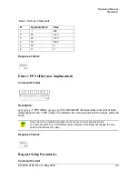
Page 28: ...ed to the 1 PPS output It is added to the unit zero point and the resync side load value Response Format Request Setup Parameters Command Format Note 1 Start up Parameters N Dynamic Gain Time 1 1 360 2 99 1140 3 60 1740 4 30 2760 5 20 0 6 11 0 Note There is a hardware limitation on the resync control of approximately 12 microseconds Any 1 PPS offset values outside of this range will change the zer...

Page 29: ...econds 9 15 Dynamic Gain Offset Factor DOoooo in nanoseconds 5 25 Km KM kkkkkk 9 31 Ko1 KO1 nnnnnn 10 41 Ko2 KO2 oooooo 10 52 Disgain DGddddd 7 63 Resync Threshold RTrrrrrr rrr in microseconds 12 71 Resync Delay RDdddd in microseconds 6 84 Rate Threshold RArrrrrr rrr in microseconds 12 91 Burst BUx x 0 Off x 1 On 3 104 Default Calibrate Unit CZrr rrrr in microseconds 9 108 1PPS Offset POyyyyyy yyy...

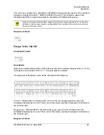
Page 30: ...t threshold x 1 Low 2 5 volt input threshold Response Format Enter Programmable Delay Value Command Format Description The yyy is a number from 000 to 255 The number is the delay value sent to a programmable delay The programmable delay moves the 1 PPS outputs and allows them to be aligned to the 10 MHz Response Format Enter Oscillator Control Range not implemented Command Format Description ...

Page 31: ...he extra data is included The response to the status command is changed to the following Frr rrrrrr Filtered rate in microseconds rr rrrrrr is the an average frequency rate error calculated internally by the unit This is one of the values used by the program to determine the dynamic gain Oyyyyyy yyy Filtered offset in microseconds yyyyyy yyy is the an average time error calculated internally by th...

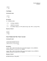
Page 32: ...nnnnn Base number for the filtered rate exponential integrator nnnnnn 000000 to 999999 represents a number from 0 to 0 999999 oooooo Base number for the filtered offset exponential integrator oooooo 000000 to 999999 represents a number from 0 to 0 999999 Response Format x 0 not doing a calibration x 1 calibration in progress x last calibration failed no 1 PPS cable missing noisy 1 PPS or wrong 1 P...

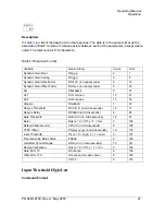
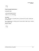
Page 33: ...c Gain Factors Command Format Description Rrr rrrr Rate Factor the normalizing value in nanoseconds for rate when calculating the next dynamic gain Oooo Offset Factor the normalizing value in nanoseconds for offset TI when calculating the next dynamic gain Response Format ...

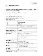
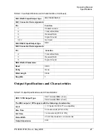
Page 34: ... 2 5 amps at initial turn on and 1 4 amps after stabilization E Power Return 5401 Fuse 10 amp fast blow 3 AG 5402 AC Power Input J1 Type IEC connector Using the standard power supply Input Voltage 5401 DC 18 V to 36 VDC MIL STD 704 80 W warmup 40 W steady state 5402 AC 90 to 240 VAC 47 440 Hz 80 W warmup 40 W steady state 5402 Fuse 3 amp fast blow Microfuse DRO 1 PPS Input Type 5401 Isolated SMA J...

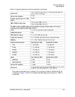
Page 35: ...nction 2 Transmitted Data 3 Received Data 5 Signal Ground DRO RS 232 Parameters Baud 9600 Parity None Word Length 8 Bits Stop Bits 1 Table 5 Output Specifications and Characteristics DRO 1 PPS Output Type 5401 Isolated SMA J1 J6 5402 Isolated BNC J4 J9 The DRO outputs 1 PPS signals with the following characteristics Level 3 V peak into 50Ω TTL compatible Rise Time 5 nanoseconds 20 to 80 Fall Time ...

Page 36: ... 12 RMS 1000 seconds while disciplining Stability 2 5 x 10 12 Alan Deviation 100 seconds Quiescent Phase Noise Symmetricom 5401 Symmetricom 5402 1 Hz 94 dBc Hz 85 dBc Hz 10 Hz 110 dBc Hz 100 dBc Hz 100 Hz 140 dBc Hz 130 dBc Hz 1000 Hz 147 dBc Hz 140 dBc Hz 10 kHz 152 dBc Hz 145 dBc Hz Spurs Symmetricom 5401 Symmetricom 5402 Harmonic 40 dBc 40 dBc Non Harmonic 50 dBc 50 dBc Port to Port Isolation 9...

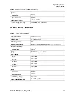
Page 37: ...us see Figure 6 Table 7 5402 Indicators Front Panel Power LED Indicates power applied to the unit see Figure 7 Table 8 DRO Internal Time Bases LPRO Low Profile Rubidium Oscillator Output Waveform 10 MHz sine wave Output Level 0 55 VRMS into 50 Output Impedance 50 Short Term Stability t 1 second 2 5 x 10 11 t 10 seconds 0 8 x 10 11 t 100 seconds 0 25 x 10 11 Aging 5 x 10 11 month Phase Noise 1 Hz 7...

Page 38: ...sine wave Output Level 0 5 VRMS into 50 Output Impedance 50 Temperature Stability 3 x 10 8 over a temperature range of 20ºC to 70ºC Short Term Stability t 1 second 5 x 10 11 Aging 5 x 10 10 day 1 5 x 10 7 year Phase Noise 10 Hz 120 dBc Hz 100 Hz 145 dBc Hz 1000 Hz 160 dBc Hz 10 kHz 165 dBc Hz 50 kHz 168 dBc Hz Spurs Harmonic 20 dBc Non Harmonic 20 dBc Input Voltage Range 12 VDC Input Power Quiesce...

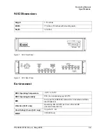
Page 39: ...PN 8500 0150 Rev A May 2005 31 Operating Manual Specifications 5401 Dimensions Figure 6 5401 Mounting Dimensions 5401 Weight Approximately 8 pounds 5402 Weight Approximately 10 pounds ...

Page 40: ...h 17 inches 19 inches with mounting ears Depth 12 inches DRO Operating Temperature 20ºC to 50ºC DRO Operating Humidity 95 non condensing up to 50ºC EMI FCC and CE EN55022 Class B for Conducted and Radi ated Emissions Vibration 5401 only Operating MIL E 5400 per Curve IIA and IIIB remains locked to 5G Crash Safety Shock 5401 only 30 g s for 11 ms MTBF 100 000 hours ...

Reviews: