background image

2-7

Installation

Pole Mounting

1.

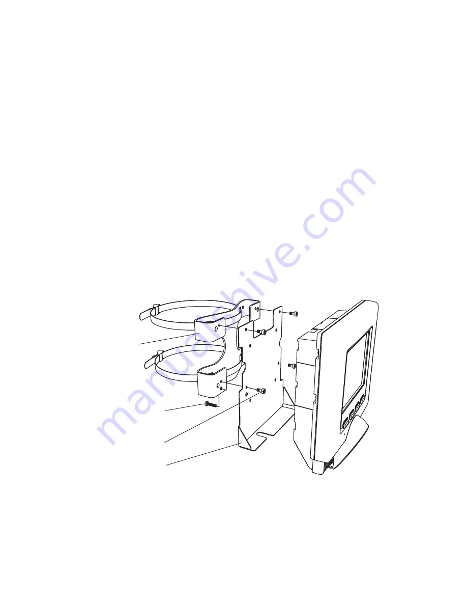
To install the Pole Mounting Kit, wrap the pole mount straps around the pole and 
tighten.

2.

Secure the connector port cover to the pole mount bracket using the four shoulder 
screws.

3.

Connect the cables to the MK2000 (see Figure 1-3 on page 1-5) and ensure the 
cables have been routed and secured correctly. Cables that are incorrectly 
mounted or secured may become pinched (see Figure 2-4 on page 2-6) when the 
terminal is attached to the Connector/Port Cover. 

4.

Position the MK2000 keyholes (on the back housing, see Figure 1-2 on page 1-4) 
over the shoulder head bolts and slide the MK2000 to the left and down to secure 
in place, see Wall Mounting Kit on page 2-5 and Mounting Directions on page 2-5.

5.

After the MK2000 is installed, screw one 8-32 pan head locking screw into the pole 
mount bracket bottom left tab, see Figure 2-5 on page 2-7. Hand tighten the locking 
screw or for additional security use a nylon locknut (not included). The locking 
screw prevents removal of the terminal. 

Figure 2-5.  Pole Mount Kit

Bracket: 

Locking Screw

Connector/Port Cover

Shoulder Screws (4)

Pole Mount

Summary of Contents for MK2000 MicroKiosk

Page 1: ...Product Reference Guide MK2000 MicroKiosk ...

Page 2: ......

Page 3: ...MK2000 MicroKiosk Product Reference Guide 72 57772 01 Revision A June 2003 ...

Page 4: ...ork from a licensed program or use a licensed program in a network without written permission from Symbol The user agrees to maintain Symbol s copyright notice on the licensed programs delivered hereunder and to include the same on any authorized copies it makes in whole or in part The user agrees not to decompile disassemble decode or reverse engineer any licensed program delivered to the user or...

Page 5: ... 1 MK2000 Parts 1 2 Touch Screen LCD 1 2 Speakers and Microphone 1 2 Scanner Window 1 2 Function Buttons 1 2 Access Covers 1 2 External Ports 1 5 MK2000 Features 1 7 Programmable Function Buttons 1 7 Bar Code Scanner 1 7 Software 1 7 Touch Screen 1 7 Magnetic Strip Reader Optional 1 7 Memory 1 7 Connectivity Options 1 7 Two Expansion Card Slots 1 7 Power Options 1 8 Mounting Options 1 8 Signage Op...

Page 6: ... MK2000 Unpacking 2 1 Installation Overview 2 2 MK2000 Mounting 2 3 MK2000 Wall Mounting Options 2 4 Pole Mounting 2 7 VESA Mounting 2 8 Power 2 9 AC Power Supply Connection 2 9 Power Over Ethernet Connection 2 9 Communication Interfaces 2 10 Wired Ethernet 2 10 Wired RS 485 Setup 2 13 Wired RS 232 Setup 2 14 Peripherals 2 16 Signage 2 16 COM Port 2 19 Connector Pin Outs 2 19 Ethernet Bias T Port ...

Page 7: ...emoving The Configuration Utility 3 16 Updating The Configuration Utility 3 16 Chapter 4 Resident Demo Application Overview 4 1 Resident Demo Application Functionality 4 2 Demo Application Versions 4 3 Resident Demo Application 4 3 Laptop Driven Demo Application 4 3 Demo Application Bar Codes 4 3 Installing the Resident Demo Application 4 4 Bypass Application Auto Boot 4 4 Delete The Current Resid...

Page 8: ...rotected Mode 6 2 Gatekeeper 6 3 Network Time Update SNTP Client 6 6 Inactivity Application Screen Saver 6 8 Chapter 7 User Applications Overview 7 1 Software Development Environments 7 1 Browser Applications 7 2 Windows CE Applications 7 2 Windows Applications via Terminal Server Client 7 2 VT220 Emulation Support for MK1000 Legacy Applications 7 3 PCK Emulation Support for MK1000 Legacy Applicat...

Page 9: ...ation Screens B 9 Demo Setup Text File B 23 Appendix C Demo Application Bar Codes Demo Application Bar Codes C 1 Appendix D Terminal Configuration Manager TCM Introduction D 1 Starting Terminal Configuration Manager D 2 Defining Script Properties D 4 Creating the Script for the Hex Image D 5 Open a New or Existing Script D 5 Copy Components to the Script D 6 Save the Script D 6 Building the Image ...

Page 10: ...ng System Upgrade E 2 IPL Menu Navigation E 3 OS Upgrade E 4 IPL Mode OS Upgrade Procedures E 4 Monitor Upgrade E 8 Monitor Upgrade Procedures E 8 Partition Table E 12 Partition Table Upgrade Procedures E 12 Demo Application Install Upgrade E 15 Appendix F Troubleshooting Troubleshooting F 1 Read MK2000 Settings F 4 Troubleshooting Notes F 4 Glossary Index Feedback ...

Page 11: ...00 features and scanning modes Chapter 2 Installation describes the hardware setup and installation of the MK2000 Chapter 3 Setup and Configuration describes the MK2000 configuration steps Chapter 4 Resident Demo Application describes the browser based Resident Demo Application Includes an operational overview of the MK2000 using the Demo application Chapter 5 Updating Data describes the tools tha...

Page 12: ...rview TCM is used to specify and load files into the flash memory of the MK2000 using the terminal s Initial Program Loader IPL Appendix E Upgrade Procedures provides instructions on using the IPL mode to upgrade the MK2000 OS Operating System Glossary provides definitions of technical terms used in this document Notational Conventions This document uses these conventions User refers to anyone usi...

Page 13: ...04 Service Information For equipment problems contact the Symbol Support Center Before calling have the model number and serial number at hand Call the Support Center from a phone near the equipment so that the service person can try to talk you through the problem If the equipment is found to be working properly and the problem is symbol readability the Support Center will request samples of your...

Page 14: ...side Singapore 65 337 6588 Outside Singapore Australia Symbol Technologies Pty Ltd 432 St Kilda Road Melbourne Victoria 3004 1 800 672 906 Inside Australia 61 3 9866 6044 Outside Australia Austria Österreich Symbol Technologies Austria GmbH Prinz Eugen Strasse 70 2 Haus 1040 Vienna Austria 01 5055794 0 Inside Austria 43 1 5055794 0 Outside Austria Denmark Danmark Symbol Technologies AS Dr Neergaar...

Page 15: ...20 1835 Inside Mexico 52 5 520 1835 Outside Mexico Netherlands Nederland Symbol Technologies Kerkplein 2 7051 CX Postbus 24 7050 AA Varsseveld Netherlands 315 271700 Inside Netherlands 31 315 271700 Outside Netherlands Norway Norge Symbol s registered and mailing address Symbol Technologies Norway Hoybratenveien 35 C N 1055 OSLO Norway Symbol s repair depot and shipping address Symbol Technologies...

Page 16: ...uide go to http www symbol com manuals Sweden Sverige Letter address Symbol Technologies AB Box 1354 S 171 26 SOLNA Sweden Visit shipping address Symbol Technologies AB Solna Strandväg 78 S 171 54 SOLNA Sweden Switchboard 08 445 29 00 domestic Call Center 46 8 445 29 29 international Support E Mail Sweden Support se symbol com 1Customer support is available 24 hours a day 7 days a week ...

Page 17: ...sed as an electronic billboard for instant in store merchandising and multimedia presentations to promote seasonal sales in store promotions and upcoming events The touch screen and programmable function buttons can enhance in store applications and allow for customer interaction Two Demo Applications are available the Resident Demo Application MK2000RDEMOAPP x xx and the Laptop Driven Demo Applic...

Page 18: ...ne which can be used for recording audio Scanner Window The scanner window protects the scan engine Function Buttons The MK2000 has four programmable function buttons shown in Figure 1 1 on page 1 3 The buttons are functionally identified A B C and D from right to left for reference purposes in this document only the alphabetic button labeling is not physically present on the MK2000 These buttons ...

Page 19: ...1 3 MK2000 Introduction Figure 1 1 MK2000 Front View Touch Function Speakers 2 Scanner Window Button D Microphone Function Button A Function Button B Function Button C Screen ...

Page 20: ... damaging sensitive components Proper ESD precautions include but are not limited to working on an ESD mat and ensuring that the operator is properly grounded Failure to apply proper ESD precautions may cause damage to the unit and could potentially void your warranty Keyhole Mounts 4 VESA Mounts 4 Access Cover Accessory Bay Connections PCMCIA Access Cover Vertical Cable Run Access Cover Compact F...

Page 21: ...ee Figure 1 3 Power Ethernet Bias T Power over Ethernet RS485 Line out Left and Right External Speakers Headphones Printer Scanner RS 232 powered BIAS T BIAS T ETHERNET ETHERNET VDC VDC 12 24 12 24 RS 485 RS 485 PRINTER PRINTER SCANNER SCANNER AUDIO AUDIO Power RS 485 Ethernet Bias T Line Out Left and Right External Speakers Headphones Jack Printer Scanner RS 232 ...

Page 22: ...port enabled RS 485 RS 485 10 conductor RJ 45 plug is sometimes termed the Multidrop LAN since it can connect several devices in a LAN network environment These devices are all connected to a single pair wire i e transmit and receive share the same two wires Line out Left and Right External Speakers Provides connections 3 5 mm for left and right external speakers Each line is powered 2 2 watts Int...

Page 23: ...m designed applications Magnetic Strip Reader Optional The three track Magnetic Strip Reader MSR provides the capability to read Magnetic Strip Cards Memory The MK2000 standard system configuration contains 64 MB flash 32 MB DRAM The Flash Memory is non volatile and is responsible for storing the system firmware The Dynamic Random Access Memory DRAM is used for storage of system parameters user pr...

Page 24: ...lat Panel Monitor Physical Mounting Interface FPMPMI mounting standards Signage Optional A user designed foam core sign can be attached to the MK2000 using the optional Signage Mounting Kit The Signage Mounting Kit placard mounting brackets will accommodate foam core or other material signs in the range from 1 8 to 3 8 in thickness see Signage on page 2 16 Software Development Kit SDK The MK2000 S...

Page 25: ... This is a highly efficient omnidirectional scan pattern which decodes 1D and EAN UCC reduced space symbologies in any orientation Note While in this mode the MK2000 does not decode 2D bar codes like PDF417 Always Raster Scan Pattern Directly opens the laser to a full sized Raster pattern Decodes 1D PDF417 RSS and Composite Codes Smart Raster Scan Pattern Creates a single scan line which opens ver...

Page 26: ...lar Reflection on page 1 14 Hold the bar coded item close for small bar codes and farther away for large bar codes Cyclone Omnidirectional In Cyclone Omnidirectional mode the scan pattern is set to decode standard and EAN UCC reduced space symbologies in any orientation This mode can not be used to decode 2D bar codes like PDF417 Figure 1 4 Cyclone Omnidirectional Pattern ...

Page 27: ...e bar code Figure 1 5 Smart Raster Scanning Pattern When using the Raster pattern the pattern must cover the top and bottom of the 2D symbol If it does not completely cover the bar code pull the bar code further away until the pattern completely covers the bar code Make sure the scan pattern extends at least three quarters of an inch beyond the edges of the bar code Figure 1 6 Raster Pattern Expan...

Page 28: ...ows and then slowly back upward to the top Alternatively move the bar code further away from the scanner until the scan pattern covers a larger portion of the bar code in the vertical direction Figure 1 7 Moving Scan Pattern Upward and Downward on Tall PDF417 Bar Code The scan beam does not have to be perfectly parallel with the top and bottom of the symbol up to a 4o tilt is permitted Ensure the ...

Page 29: ...oes not cause specular reflection see Specular Reflection on page 1 14 Hold the bar code close for small bar codes and farther away for large bar codes When using the single scan line pattern aim the scan line at the middle of the 2 D portion The scan pattern will open up to an optimized Raster pattern and decode both the 2 D and standard bar code portion of the composite code Figure 1 8 Composite...

Page 30: ...ccessful decode Practice quickly shows what tolerances to work within Figure 1 9 Avoiding Specular Reflection When scanning a 1D bar code there is only a small specular dead zone to avoid 2o from the direct laser beam The specular dead zone is larger for scanning PDF417 9o from the direct laser beam However the scanner is not effective if its beams hit the bar code s surface at an angle greater th...

Page 31: ...eps Mounting Providing Power Communications Interfaces Installing Accessories Peripherals Signage Connector Pin Outs MK2000 Unpacking Remove the MK2000 from its packing and inspect it for damage Keep the packing it is the approved shipping container and should be used if the MK2000 ever needs to be returned for servicing ...

Page 32: ...Wireless Ethernet 2Mb or 11Mb RF Wired RS 485 serial cable Wired Printer Scanner RS 232 serial cable Refer to Communication Interfaces on page 2 10 4 Select optional peripherals Printer External hand held scanner Printer Scanner RS 232 Communication Devices Refer to Peripherals on page 2 16 5 For Configuration settings refer to the Configuration Utility on page 3 9 To configure the communications ...

Page 33: ...NING IT ALSO HAS THE ABILITY TO BE PLACED INTO A FLUSH PANEL KIOSK ENVIRONMENT KEYHOLE SLIDE ON MOUNTING BRACKETS PHYSICAL MOUNTING INTERFACE STANDARD MOUNTING BRACKETS OR SYMBOL S ALL DIMENSIONS PROVIDED IN INCHES THE MK2000 IS DESIGNED TO BE USED WITH VESA FLAT PANEL MONITOR NOTES 68 8 51 0 41 1 65 1 28 1 81 8 92 0 68 7 57 10 74 3 51 5 00 1 4 MOUNTING FACE VESA KEYHOLE 0 312 DIA HEAD MOUNTS 0 19...

Page 34: ...nd secured correctly see Figure 2 4 on page 2 6 Cables that are incorrectly mounted or secured may become pinched when the terminal is attached to the Connector Port Cover Install the Connector Port Cover place the keyholes on the back housing over the shoulder head bolts protruding from the plate and slide the MK2000 to the left and down to secure in place see Wall Mounting Kit on page 2 5 and Mo...

Page 35: ...2 5 Installation Figure 2 2 Wall Mounting Kit Figure 2 3 Mounting Directions Shoulder Mounting Plate Tab Head Bolts 4 Lock Screw Connector Port Cover Move to the left first Move down second ...

Page 36: ...nt Kit on page 2 4 With the exception that an opening is cut 8 63 min height x 8 0 min width in a wall or kiosk and the back housing is placed into the opening see Wall Mounting Kit on page 2 5 and Mounting Directions on page 2 5 Symbol does not provide hardware to support this installation Recessed mounting may degrade the wireless network performance Vertical Cable Run ...

Page 37: ...tached to the Connector Port Cover 4 Position the MK2000 keyholes on the back housing see Figure 1 2 on page 1 4 over the shoulder head bolts and slide the MK2000 to the left and down to secure in place see Wall Mounting Kit on page 2 5 and Mounting Directions on page 2 5 5 After the MK2000 is installed screw one 8 32 pan head locking screw into the pole mount bracket bottom left tab see Figure 2 ...

Page 38: ...he Shelf stands search the internet for VESA Mount Symbol also offers an optional VESA Mounting Kit The kit includes a Connector Port Cover which provides enhanced security by covering the MK2000 s cables and ports see Figure 2 6 on page 2 8 1 Route and secure the cables confirm that the cables are not pinched see Figure 2 4 on page 2 6 Position the Connector Port Cover between the 3rd party VESA ...

Page 39: ...n the power installation is completed return to Installation Overview on page 2 2 and proceed with step 3 Select the data communications method Power Over Ethernet Connection The Ethernet cable in the Power over Ethernet POE installation has two components power and data The Ethernet cable can be used only to supply power it can be used only to supply data or it can be used to supply both power an...

Page 40: ...sktop see MK2000 Protected Mode on page 6 2 Wired Ethernet The MK2000 communication options include a wired Ethernet connection 10Base T cable When a wired Ethernet connection is used the MK2000 can be powered either using the MK2000 s Symbol approved AC power supply connected to an AC outlet or by receiving Power over Ethernet through the Ethernet cable Wired Ethernet Power via AC Outlet With thi...

Page 41: ...xternal power supply connected to the power port on the MK2000 Using two power sources may damage the MK2000 and or the network 1 Connect the Ethernet cable to the MK2000 Ethernet Bias T port see Figure 1 3 on page 1 5 2 Ensure the Ethernet cable is terminated according to Table 2 2 on page 2 20 3 Plug the other end of the Ethernet cable into the Bias T POE module 4 Connect a patch cable from the ...

Page 42: ...000 Power Over Ethernet Network Connectivity Customer Switch Hub DC Power Supply DC Power Supply Category 5 Patch Cable 100m Category 5 Specification Limit Customer Patch Panel AP PSBIAS T AP PSBIAS T MK2000 Category 5 MicroKiosk Category 5 Category 5 Patch Cable ...

Page 43: ...e 2 15 for an illustration of the two wire multidrop differential signal When installing an RS 485 configuration ensure each MK2000 is connected directly to the RS 485 bus see Figure 2 8 Figure 2 8 Connector Block The cable required for an RS 485 installation should meet or exceed the following specifications 1 twisted pair 26 AWG 7 34 tinned copper twisted pair foil wrapped 100 coverage nominal i...

Page 44: ...e 1 5 for port locations Ensure the serial cable is terminated according to the RS 485 Port Connections described in Table 2 3 Plug the other end of the RS 485 serial cable into the converter box 3 When the data communications installation is completed return to Installation Overview on page 2 2 and proceed with step 4 select accessories Wired RS 232 Setup The MK2000 can communicate with a host us...

Page 45: ...mple RS 232 GWG 1 2 W 100Ω 100Ω Rt 1 2 W 1 2 W 100Ω 100Ω 4000 Ft Maximum Termination Resistors at Both Ends RS 232 RS 485 Conversion Box Rt GWG GWG 100Ω 100Ω 100Ω 100Ω 1 2 W GWG Green wire ground or power system ground Circuit ground or circuit common Rt 120Ω 1 2W GWG ...

Page 46: ...re the cable is terminated properly For Printer Scanner RS 232 Port Connections pin outs see Table 2 4 2 If not already connected plug the other end of the cable into the auxiliary device Signage The Signage placard mounting brackets and attaching screws are provided in the Signage Mounting Kit The mounting brackets will accommodate foam core or other material signs mounted on the MK2000 in the th...

Page 47: ...2 17 Installation Figure 2 10 Placard Mounting Brackets Installation Placard Mounting Brackets ...

Page 48: ...2 18 MK2000 MicroKiosk Product Reference Guide Figure 2 11 Sign Installation MK2000 Display Signage ...

Page 49: ...able 2 2 through Table 2 4 describe the MK2000 connector pin outs see Figure 1 3 on page 1 5 for port locations Figure 2 12 10 Pin Connector Port Table 2 1 COM Port COM Port COM1 RS 485 COM4 RS 232 no power COM6 RS 232 with 5 VDC Pin 10 Pin 1 10 Pin ...

Page 50: ... MK2000 through a single Ethernet cable If power to the MK2000 is being provided via POE do NOT use the Symbol approved AC power supply Table 2 2 Power over Ethernet Connections Pin Description Pin 1 Reserved Do not Use Pin 2 TXD Pin 3 TXD Pin 4 RXD Pin 5 Bias T VCC Pin 6 Bias T VCC Pin 7 RXD Pin 8 Bias T GND Pin 9 Bias T GND Pin 10 Reserved Do not Use Used only with Power over Ethernet ...

Page 51: ...d Printer Scanner RS 232 port specification are RJ 45 jack 10 conductor 5V 500mA Table 2 3 RS 485 Connector 10 Pin Pin Description Pin 1 RS 485 Pin 2 RS 485 Pin 3 Reserved Pin 4 Reserved Pin 5 USB PWR Pin 6 USB Pin 7 USB Pin 8 RS 485 Pin 9 GND Pin 10 RS 485 Table 2 4 Printer Scanner RS 232 Connector 10 Pin Pin Description Pin 1 5V Pin 2 Not Used Pin 3 RXD input Pin 4 Not Used Pin 5 RTS output Pin ...

Page 52: ...2 22 MK2000 MicroKiosk Product Reference Guide ...

Page 53: ...eters can also be set using the Control Panel Setup and configuration steps covered include Control Panel Configuration Parameters File System Structure Description Managing the Startup Process Startup Program Configuring User Application s Reliable Sequencing of Application Programs Reset Function Control Panel Settings Stylus Settings Specifying an ESSID For a Wireless Network Connection Configu...

Page 54: ...ble 3 1 Table 3 1 Control Panel Configuration Parameter Configuration Parameter Description Backlight See Stylus Settings on page 3 8 Brightness Button Settings Button Definitions see Configuration Utility on page 3 9 Button mappings Trigger Time Daylight Savings Time See Date and Time on page 3 7 Auto Adjust Time Inactivity Manager See Inactivity Manager on page 3 7 Idle Time Before Launch Inacti...

Page 55: ...n user application slots with identical parameters Each slot is under a group called X application launched where X is first second etc see Configuring User Application s on page 3 5 Application Path Arguments Delay Before Launch Waiting For Completion Volume and Sounds See Volume and Sounds on page 3 7 Default Volume Keypress Sounds Screen Tap Sounds Sound Scheme Sounds Generated By Table 3 1 Con...

Page 56: ...n of the system s RAM for a writeable file system and allows read only files to be replaced in flash with new versions in RAM The files aren t actually replaced when a replaced file is referenced Windows CE provides the RAM version If the RAM version is deleted the ROM version still exists Table 3 2 summarizes the top level folders of the MK2000 Non Object Store folders will only be present if the...

Page 57: ...or descriptions of each parameter Programs launch one after the other with no delay unless either Delay Before Launch or Waiting For Completion parameters are set Table 3 3 Startup Program Parameter Descriptions Parameter Description Application Path The Application Path is the full run path to the executable This must be defined for the entry to be processed i e do not just specify a delay File t...

Page 58: ...For Completion flag for this program and run it before running the main application s For example use the program to confirm connection to a database server or web site that the application relies on before launching the application This is suitable for web based applications where lack of control over the application software limits the ability to build contingency into the startup process For fa...

Page 59: ...ing System Initialization Phase 1 screen appears The A and D buttons must be held down before the message changes to Phase 2 3 When the Enter Password prompt appears enter DDBAC and touch OK on the screen or simultaneously press the A and B buttons for Enter 4 The MK2000 enters Protected Mode and the Win CE desktop appears Control Panel Settings Settings include the following Backlight Settings Bu...

Page 60: ...less Network Connection The ESSID for the Spectrum24 radio card is set using the Symbol Mobile Companion application It is saved with the other values of the current configuration As always if the value is changed save the new configuration To set the value use the Configuration Utility Communications S24 802 11b ESSID or perform the following steps from Windows CE Protected Mode 1 To run Mobile C...

Page 61: ...d side similar to Windows Explorer Users navigate to and select the desired parameter The right hand pane then displays editing controls suitable for editing the parameter data When the user has completed customizing the MK2000 settings the information is saved to a configuration file and can then be loaded on to the MK2000 s non volatile storage location In non volatile storage the configuration ...

Page 62: ...ion Utility install file and save it on the PC s hard drive Select Start Run from the Windows task bar and use the Browse button locate the Configuration Utility install file and select OK Follow the instructions presented by the installation wizard 1 The Configuration Utility First Install Screen welcomes the installer and provides copyright information select Next to continue Figure 3 1 Configur...

Page 63: ... Enter a new install path or accept the default path and select the Configuration Utility users Select Next to continue Figure 3 2 Configuration Utility Select Folder Screen 3 The Configuration Utility Confirm Install Screen allows the installer to confirm the installation select Next to continue Figure 3 3 Configuration Utility Confirm Install Screen ...

Page 64: ...croKiosk Product Reference Guide 4 The Configuration Utility Install Complete Screen confirms the installation was completed successfully select Close to exit Figure 3 4 Configuration Utility Install Complete Screen ...

Page 65: ...guration Utility see Figure 3 5 on page 3 13 The main configuration category listings are provided Communication System Configuration Update DHCPConfig An overview of the editing functions is provided see Edit Data Entry Formats on page 3 14 A discussion of the DHCP editing options is also provided see Editing DHCP Options on page 3 15 Figure 3 5 MK2000 Configuration Utility ...

Page 66: ...en viewing the registry file it may not match the selection Bit Fields A number of items that are presented in a list with check boxes beside each item Multiple items can be selected from none to all Each selected item affects the value stored The value stored is a single number so the selections will not match what is in the generated file Multiple Text The fields allow multiple free form strings...

Page 67: ...luded in the saved Configuration File The edit button is used to access both the send and receive option selections Two windows are provided the first contains the Available Options selections and the second lists the options that have already been selected To add a receive option highlight the option and select the Add button to move the item to the items selected for receive window To Remove an ...

Page 68: ... options From the Send tab select new options from the pull down menu and tap on the Enable Option box The Enter value data entry box appears Enter the option value s desired Reverse the procedure and clear the Enable Option box to remove the selected options Removing The Configuration Utility Use the Windows Add Remove a program utility to remove the Configuration Utility from the desktop PC Upda...

Page 69: ...ation available for download either individually or as part of the SDK at http devzone symbol com The purpose of the Resident Demo Application is to provide a visual and audible demonstration of the MK2000 s capabilities The Resident Demo Application can be set to launch automatically on MK2000 boot up Figure 4 1 Main Screen ...

Page 70: ...ionality of the MK2000 in a retail environment The Resident Demo Application is functionally divided into Customer Applications and Store Operations The Customer Application screens provide Advertising Attract Mode Price Verification Music Listen Station Alternate Language Information Loyalty Program The Store Operations screens provide Item Information In Store Messaging Text and Voice Voice Reco...

Page 71: ...op Driven Demo Application The Laptop Driven Demo Application see Setting Up The Laptop Driven Demo Application on page B 4 is a browser based thin client application hosted by a laptop desktop computer via a network connection For more about this version of the Demo Application and what features can be modified or customized see Laptop Driven Demo Application on page B 1 The Laptop Driven Demo Ap...

Page 72: ...rs The A and D buttons must be held down before the message changes to Phase 2 3 When the Enter Password prompt appears enter DDBAC and touch OK on the screen or simultaneously press the A and B buttons for Enter 4 The MK2000 enters Protected Mode and the Win CE desktop appears Delete The Current Resident Demo Application Version 1 Double tap the My Computer icon on the CE desktop 2 Double tap the...

Page 73: ...g an application simultaneously hold down buttons A and D just after the blue Performing System Initialization Phase 1 screen appears The A and D buttons must be held down before the message changes to Phase 2 2 When the Enter Password prompt appears enter DDBAC and touch OK on the screen or simultaneously press the A and B buttons for Enter 3 The MK2000 enters Protected Mode and the Win CE deskto...

Page 74: ...atically launch Exit the Resident Demo Application and Launch the Windows CE Desktop 1 To perform a cold boot press and hold buttons B and C until the display goes blank typically 15 seconds then release buttons see Figure 1 1 on page 1 3 The MK2000 reboots 2 To prevent the MK2000 from entering an application simultaneously hold down buttons A and D just after the blue Performing System Initializa...

Page 75: ...ch screen buttons displayed over the 4 function buttons The Customer Application Screens demonstrate the customer support features Customer Application Screens on page 4 8 Main Menu Bar on page 4 8 Scanning Bar Codes on page 4 8 Attract Mode on page 4 9 Price Verification on page 4 10 Price Verification Menu Bar on page 4 12 Loyalty Program on page 4 13 The Store Operations Screens demonstrate som...

Page 76: ...ar Scanning Bar Codes A bar code item s SKU employee badge or loyalty card can be scanned from any point within the application However 2D bar codes can only be scanned from the Scan a 2D bar code screen see page 4 20 For example after a store employee has scanned an item s SKU for price lookup and they are on the price verification screen they can scan their employee badge to directly access the ...

Page 77: ...e and displays a slide show Attract Mode is automatically entered after a period of inactivity on any screen the slides are displayed in preset intervals Slide Show screen saver While the slide show displays the Main Menu Bar see page 4 8 is visible The slides are displayed serially Figure 4 3 Slide Show Screens ...

Page 78: ...ty Program enabled Requires the Loyalty Program bar code to access special Loyalty Program product information Price Verification screen Non Loyalty Program Displays standard non Loyalty Program product information Price Verification screen Audio Enabled Figure 4 4 Loyalty Program Enabled Price Verification Screen Figure 4 5 Non Loyalty Program Price Verification Screen ...

Page 79: ...abled Price Verification screen provides an audio listening station to the price verification screen Two Volume Control Buttons Louder Quieter Pause Home returns to Attract Mode see page 4 9 Figure 4 6 Audio Enabled Price Verification Screen ...

Page 80: ...rnate Language The MK2000 Demo Application s default primary language is English and the default alternate language is Spanish On the Price Verification screen the title above button 1 labels the alternate language Once selected the alternate language remains in effect until the screen is exited or until another button is pressed Selecting button 1 on the Price Verification screen changes the text...

Page 81: ...page 4 8 or from the Price Verification screen see page 4 10 displays the Loyalty Program screen Figure 4 8 Loyalty Program Screen Scanning the Loyalty Program see Demo Application Bar Codes on page C 1 provides details about the customer s Loyalty Program account status Figure 4 9 Loyalty Program Account Status ...

Page 82: ...ailable from the Store Operations screen is provided below While on this screen the internal scan engine is disabled The Store Operations Menu Bar displays the following button titles Item Info see page 4 14 Messages see page 4 15 Scan 2D see page 4 20 Home returns to Attract Mode see page 4 9 Figure 4 10 Store Operations Screen Item Information The Item Information selection is a non functional b...

Page 83: ...n a message the information displayed in the row is highlighted Selecting a Voicemail message displays the Voicemail Options Screen see page 4 16 and selecting a text message in this Demo Employee Bulletin displays the Text Messaging Screen see page 4 19 Select Options Up Arrow to scroll up on the Item list Down Arrow to scroll down on the Item list Open to select an item on the Item list and proc...

Page 84: ...displays the Voicemail Options screen The Voicemail Options Screen is used to listen or respond to a voice message Select Options Right Pointer to play the message Reply to enter the Voicemail Response Screen see page 4 18 Delete to delete the message Back to return to the previous messaging screen Figure 4 12 Voicemail Options Screen ...

Page 85: ...l Playback screen The Voicemail Playback Screen is used to listen to and or reply to a message Select Options First Speaker button increases volume Second Speaker button decreases volume Double bar button to pause the recorded message Square returns to the Voicemail Options Screen on page 4 16 Figure 4 13 Voicemail Options Screen ...

Page 86: ...MK2000 s built in microphone see Figure 1 1 on page 1 3 This screen can be used to record a message and play the message back Select Options Circle Button press Circle Button and speak into the microphone to record a reply message press Circle Button again to stop recording Right Pointer to play the recorded message Send to send the message Back to return to the Voicemail Options Screen see page 4...

Page 87: ...reen displays the Text Messaging screen The Text Messaging Screen is used to view a text based message Select Options Delete to delete the message and return to the In Store Messaging Screen see page 4 15 Back to save the message and return to the In Store Messaging Screen see page 4 15 Figure 4 15 Text Messaging Screen ...

Page 88: ...ad a 2 D bar code such as a PDF or composite code see sample 2D bar code PDF417 on page C 7 After selecting the Scan a 2D bar code button the scanning mode laser scan pattern is switched from omni directional cyclone 1 D scanning mode to 2 D scan mode When a 2D bar code is scanned and decoded the MK2000 beeps and displays the bar code data Select Home to return to the In Store Messaging Screen see...

Page 89: ...into a single partition that represents a specific area of storage Examples of partitions are the operating system or a flash file system such as platform or application Using the desktop computer comparison a partition is equivalent to a C or D hard disk drive When a partition is updated all data that was previously in its storage region is erased i e it is not a merge but rather a replacement op...

Page 90: ...ition Application Partition Data Partition Partition Table Splash Screen Monitor AirBEAM SMART The MK2000 supports AirBEAM and is shipped with Smart Client 2 1 AirBEAM Smart Client software enables automated upgrades to the operating system RF card firmware and embedded application Custom applications written by a retailer or software integrator can also be loaded onto the MK2000 using AirBEAM Air...

Page 91: ...ing Partitions and Packages AirBEAM Package Builder can be used to update and create partitions and packages Downloading Files The following tools can be used to copy a file or files to any file system on the device AirBEAM Smart FTP Server CF Card AirBEAM is the only one of these tools that can be used to update partitions which are packages of one or more files that completely fill a partition r...

Page 92: ...d by default when shipped FTP Server Registry Parameters Allow Anonymous There is no authentication of users so users do not need to have an account on the local machine Allows copying of data from device Allow Anonymous Upload Allows anonymous users to copy data to the device Root Directory Root directory Only this directory and subdirectories are accessible remotely Defaults to Is Enabled Causes...

Page 93: ...ata CF Card Files can be uploaded and or downloaded to the MK2000 from a CF card inserted in the MK2000 The CF card can then be removed and the downloaded data accessed from any device capable of reading CF card data ...

Page 94: ...5 6 MK2000 MicroKiosk Product Reference Guide ...

Page 95: ...l Non Volatile settings can be re set and saved The saved new settings are retained after power down see Configuration Utility on page 3 9 Button Definitions Backlight Touchscreen Calibration Inactivity Manager Scan Wedge Password Volume Internet Settings Selected values on the Control Panels User Application Launcher Application Password Volume and Sounds Volume tab Internet Settings General tab ...

Page 96: ...ge is a driver run during startup that imports registry files into the active registry It is the loading mechanism used by the configuration files and it is used as part of the platform and application install of additional software components see the Regmerge Copyfiles section for additional information MK2000 Protected Mode If an MK2000 has been configured to automatically launch an application ...

Page 97: ...sword is submitted and correct the Gatekeeper launches the Windows desktop If the password is incorrect or Protected Mode access was not requested and the User Application is defined it launches the Symbol Startup program Startup is responsible for running AirBEAM if present any system level programs and finally the User Application If no User Application is defined the system boots to Protected M...

Page 98: ... a button combination set its mapping to 0 Note 2 To perform a cold boot press and hold buttons B and C until the display goes blank typically 15 seconds then release buttons see Figure 1 1 on page 1 3 The MK2000 reboots Table 6 2 Remapping Buttons Button Combo Mapping Default or Permanent Hex Code A Up D 0x26 B Down D 0x28 C Left D 0x25 D Right D 0x27 AB Enter Return D 0x0D AC Alt Down pop up com...

Page 99: ...14 F3 0x72 ESCAPE 0x1B F4 0x73 SPACE 0x20 F5 0x74 PRIOR 0x21 F6 0x75 NEXT 0x22 F7 0x76 END 0x23 F8 0x77 HOME 0x24 F9 0x78 LEFT 0x25 F10 0x79 UP 0x26 F11 0x7A RIGHT 0x27 F12 0x7B DOWN 0x28 0 thru 9 are the same as ASCII 0 thru 9 0x30 0x39 MULTIPLY 0x6A A thru Z are the same as ASCII A thru Z 0x41 0x5A ADD 0x6B Shift Tab 0xC2 SEPARATOR 0x6C Alt Down 0xC3 SUBTRACT 0x6D Calibration 0xC4 DECIMAL 0x6E S...

Page 100: ...e SNTP client has three registry parameters the most important of which is the Server s setting Server s A multi string value specifying the SNTP servers to be queried The servers will be queried in order until one is successful or the list is exhausted If the device is unable to obtain a time value from a server it will use the default setting July 1 1999 12 00 00 AM An attempt to acquire a time ...

Page 101: ...egistry values hosts A comma separated list of SNTP servers to be queried The servers will be queried in order until one is successful Q Don t report any results and or problems quiet N Report all results and or problems noisy P Run the program periodically according to the period value in the registry The SNTPClient program is run as part of the MK2000 s StartUp sequence before any user programs ...

Page 102: ...n the screen Perform some action to wake me up This program is used as the default IAM Inactivity Application Manager application This Inactivity Application is designed to provide a simple example of how to implement a custom application it is not intended to be used as a final presentation tool Source code is provided in the SDK part number MK2000CESDK x xx SlideShow The SlideShow program is a s...

Page 103: ...opriate file name extensions These files will be displayed in a sequence that is determined by the file system If a slide is smaller than the screen size it will be centered on the screen and the background color will be drawn in the area around the slide If a slide is larger than the screen size it will be scaled to fit on the screen This scaling can result in a strange effect if the slide is not...

Page 104: ...6 10 MK2000 MicroKiosk Product Reference Guide ...

Page 105: ...ts The MK2000 s operating system is WinCE NET 4 1 The MK2000 allows several choices for development environments The operating system contains support for the major technologies and functions needed to develop an application in any of these environments Web Browser application Windows CE applications Unmanaged applications Windows applications via Terminal Server Client RDP VT220 Emulation PCK Emu...

Page 106: ...toolbars etc To run the final application with no toolbars status bar location etc use kioskie exe It is the same browser but without the toolbars etc The application can be developed using iesample exe and the final test using kioskie exe Windows CE Applications Windows CE applications can be grouped into two categories managed applications and Unmanaged Applications Unmanaged Applications Unmana...

Page 107: ...CK Emulation Support for MK1000 Legacy Applications A version of Symbol s PCK terminal emulation program is available Symbol Developer zone http devzone symbol com for the MK2000 This program is backwards compatible with the MK1000 s PCK emulation IBM 4690 Applications The MK2000 will communicate with IBM 4690 systems via Symbols Storewave 4690 software To communicate with Storewave the MK2000 mus...

Page 108: ...7 4 MK2000 MicroKiosk Product Reference Guide ...

Page 109: ... cm D Weight 3 5 lbs 1 6 kg typical Power 12 24 VDC 24 Watts Supports Power over Ethernet Data Ports RS 232 Powered 5V 500 mA RJ 45 Connector RS 485 RJ 45 Connector Ethernet Wired 10 100Mb base T Audio Ports Speaker Two integrated stereo speakers Head Phone Jack Standard 3 5 mm jack Stereo Line Out 2 2 watts per channel 3 5 mm jacks Microphone Located under left side of display Buttons 4 Programma...

Page 110: ...s including UPC EAN Code 39 Interleaved 2 of 5 Code 128 Codabar MSI Plessey PDF417 RSS and Composite Codes Processor Intel XScale 400 MHz Memory Flash 64 MB Flash RAM 32 MB DRAM Software Operating System Windows CE V4 1 Browser Internet Explorer Audio Video Windows Media Player Available Applications Demo Applications Resident and Laptop also see SDK PCK9100 Emulation VT220 Emulation AirBEAM On bo...

Page 111: ... 11 Mbps DS 802 11b Operating Temp 32 F to 104 F 0 C to 40 C Storage Temp 13 F to 158 F 25 C to 70 C Humidity 5 to 80 non condensing Electrical Safety Certified to UL1950 CSA C22 2 No 950 EN60950 IEC950 EMI RFI FCC Part 15 Class B ICES 003 Class B European Union EMC Directive Australian SMA Laser Safety IEC Class 2 CDRH Class II Mounting Options Conforms to VESA 100mm mounting standard Wall Mount ...

Page 112: ...A 4 MK2000 MicroKiosk Product Reference Guide ...

Page 113: ...ith the MK2000 SDK In addition both the Laptop Driven Demo Application and the Resident Demo Application are available at http devzone symbol com Laptop Driven Demo Application Resident Demo Application differences The Laptop Driven Demo Application requires the operation of a computer in addition to the MK2000 The Resident Demo Application does not require any additional external connectivity to ...

Page 114: ...Driven Demo Application Source Code The Laptop Driven Demo Application is distributed with the source code to facilitate application development The Laptop Driven Demo Application s source code targets the following MK2000 capabilities Scan Engine control turning on off and switching scan modes ActiveX Object Bar code data processing based on symbology type Developing a browser based thin client a...

Page 115: ...p_Setup txt text document LoyaltyCardSpecial txt text document MK2000Demo mdb Access database The ad image files displayed in the Attract Mode screen can be replaced by replacing slide1 jpg in the MK2000 Slideshow_images directory Additional images can also be added by creating an ads7 asp and pointing ads6 asp to it in the meta tag The meta tag in ads7 asp should point to ads asp see the source c...

Page 116: ...he Demonstration Application However the contents of the two files are different When the mkconfig reg file used by the Laptop Driven Demo Application is copied into the directory containing the mkconfig reg file used by Demonstration Application the Demonstration Application s mkconfig reg file is overwritten Answer YES to the prompt asking if the file should be overwritten Web Server Setup Copy ...

Page 117: ... the mkconfig reg file onto the MK2000 Insert the compact flash card containing the mkconfig reg file into the MK2000 CF card slot Double tap the My Computer icon on the CE desktop The contents of the CF card will be accessible via a Storage Card folder from within My Computer Use the Copy functionality under the Task bar Edit to copy the mkconfig reg file from the My Computer Storage Card folder ...

Page 118: ... 1 To prevent the MK2000 from entering the Laptop Driven Demo Application simultaneously hold down buttons A and D just after the blue Performing System Initialization Phase 1 screen appears The A and D buttons must be held down before the message changes to Phase 2 2 When the Enter Password prompt appears enter DDBAC and touch OK on the screen or simultaneously press the A and B buttons for Enter...

Page 119: ... Application Set Up and Customizing The Laptop Driven Demo Application operation is controlled by the parameters set in the Demo_App_Setup txt document see Demo Setup Text File on page B 23 This document is located in the MK2000 folder in the C Inetpub wwwroot directory Communication Modes Set Up Wired Ethernet Use config utility or open the Network and Dialup Connections control panel and open th...

Page 120: ...rtual touch screen buttons displayed over the 4 function buttons The Customer Application Screens demonstrate the customer support features Customer Application Screens on page B 9 Main Menu Bar on page B 9 Scanning Bar Codes on page B 9 Attract Mode on page B 10 Price Verification on page B 11 Price Verification Menu Bar on page B 11r Loyalty Card Program on page B 14 The Store Operations Screens...

Page 121: ...ee Modifying Button Titles on page B 7 to change the titles Scanning Bar Codes A bar code item s SKU employee badge or loyalty card can be scanned from any point within the application For example after a store employee has scanned an item s SKU for price lookup and they are on the price verification screen they can scan their employee badge to directly access the store operations menu ...

Page 122: ...t Mode and displays a slide show in 5 second intervals typical Slide Show screen saver While the slide show displays the Main Menu Bar is visible Slides displayed in this mode are located in the SlideShow_Images folder Name the slides slide 1 jpg slide 2 jpg slide 3 jpg etc The slides are displayed serially Figure 2 1 Slide Show ...

Page 123: ...faces Supported Price Verification The Laptop Driven Demo Application has three different price verification screen formats Price Verification Menu Bar The Laptop Driven Demo Application has three different types of price verification screens Loyalty Program Price Verification Non Loyalty Program Price Verification Audio Enabled Price Verification The Menu Bar enables the following functionality F...

Page 124: ...nguage Once selected the alternate language remains in effect until the screen is exited or until another button is pressed Selecting button 1 on the Price Verification screen changes the text on the screen from the primary language to the alternate language including all screen titles buttons titles and price verification field titles Print Print button is not enabled Loyalty Program See Loyalty ...

Page 125: ...ammable It is a field in the database and associated with an item s SKU The default value is the US dollar Other commonly used symbols for currency include but are not limited to European Euro British pound and Japanese yen Display An Image Display an image JPEG or BMP of the item scanned For the image of the SKU to be displayed the image name must be called out in the appropriate database field T...

Page 126: ...lty Program screen Figure 2 5 Loyalty Program Screen Scanning the Loyalty Card see Demo Application Bar Codes on page C 1 provides details about the customer s Loyalty Program account status The information provided on the Loyalty Program account status screen is programmable In this example the customer s name and status how many dollars away from a free turkey is displayed Figure 2 6 Loyalty Pro...

Page 127: ...to specify the graphic used and the text to be displayed on the Loyalty Card Program display screens To change the information on the Loyalty Card Program display screens change the LoyaltyCardSpecial txt file maleturkey gif Our Thanksgiving Turkey Drive is under way BR If you have a loyalty card for every 250 spent in the month of November you earn a free turkey BR ...

Page 128: ...s is provided see the referenced pages Select Exit to return to Attract Mode on page B 10 The Store Operations Menu Bar displays the following button titles Item Information In Store Messaging Scan a 2D bar code Exit Store Menu returns to Attract Mode on page B 10 Figure 2 7 Store Operations Screen Item Information The Item Information selection is not enabled in this Laptop Driven Demo Applicatio...

Page 129: ...scroll bar is on a message the information displayed in the row is highlighted Selecting a Voicemail message displays the Voicemail Options Screen on page B 18 and selecting a text message in this Demo Employee Bulletin displays the Text Messaging Screen on page B 21 Select Options Up scroll up on the Item list Down scroll down on the Item list Select to select an item on the Item list and proceed...

Page 130: ...mail Options screen see Voicemail Options Screen on page B 18 The Voicemail Options Screen is used to listen or respond to a voice message Select Options Play button to play the message Respond to enter the Voicemail Playback Screen on page B 19 Delete to delete the message Exit return to the previous messaging screen Figure 2 9 Voicemail Options Screen ...

Page 131: ...splays the Voicemail Playback screen The Voicemail Playback Screen is used to listen to and or reply to a message Select Options Two volume control buttons Louder Quieter Pause button to pause the recorded message Stop Exit to returns to the Voicemail Options Screen on page B 18 Figure 2 10 Voicemail Response Screen ...

Page 132: ...K2000 s built in microphone see Figure 1 1 on page 1 3 This screen can be used to record a message and play the message back Select Options Record Response press Record Response and speak into the microphone to record a reply message press Record Response again to stop recording Playback to play the recorded message Send to send the message Exit to returns to the Voicemail Options Screen on page B...

Page 133: ...e Text Messaging screen see Text Messaging Screen on page B 21 The Text Messaging Screen is used to view a text based message Select Options Delete to delete the message and return to the In Store Messaging Screen on page B 17 Back to save the message and return to the In Store Messaging Screen on page B 17 Figure 2 12 Text Messaging Screen ...

Page 134: ...ode PDF417 on page C 7 After selecting the Scan a 2D bar code button the scanning mode laser scan pattern is switched from omni directional cyclone 1 D scanning mode to 2 D scan mode The a 2D bar code is scanned the MK2000 beeps and displays the bar code data Select Return to return to the In Store Messaging Screen on page B 17 Figure 2 13 Scan a 2D Bar Code Screen Figure 2 14 2D Bar Code Data Scr...

Page 135: ...t preface are used for the alternative language text entries Table 2 2 Demo Setup Text File Demo_App_Setup txt File Contents Laptop Demo Application Variables Your Company Here CompanyName Scan Item ScanPrompt Item ItemPrompt Regularly Price Description Description Sale Price SalePrice Loyalty Discount LoyaltyDiscount Loyalty Price LoyaltyPrice Artículo AltItemPrompt Regularmente AltPrice Descripc...

Page 136: ...B 24 MK2000 MicroKiosk Product Reference Guide Regreso AltButton3 49 Button1 50 Button2 51 Button3 52 Button4 Demo_App_Setup txt File Contents Laptop Demo Application Variables ...

Page 137: ...C 1 Appendix C Demo Application Bar Codes Demo Application Bar Codes Sample bar codes are provided for use with the Demo Application Wide Screen TV 0 11048 83112 9 ...

Page 138: ...C 2 MK2000 MicroKiosk Product Reference Guide DVD Player White Correction Fluid 0 11096 38390 8 0 70330 50367 0 ...

Page 139: ...C 3 Demo Application Bar Codes Glue Stick Transparent Tape 0 71709 00166 7 0 51131 77138 3 ...

Page 140: ...C 4 MK2000 MicroKiosk Product Reference Guide Standard Staples Tylenol 0 74711 35440 0 3 00450 44909 2 ...

Page 141: ...C 5 Demo Application Bar Codes Standard Staples CD 3 12546 65021 3 0 75678 12772 4 ...

Page 142: ...C 6 MK2000 MicroKiosk Product Reference Guide Employee Badge John Ryan Code 128 Loyalty Card Clark Kent Code 39 56842 Employee Badge John Ryan 4125279101 Loyality Card Clark Kent ...

Page 143: ...C 7 Demo Application Bar Codes 2D bar code PDF417 Text Reads You have just scanned a PDF417 bar code using the MK2000 ...

Page 144: ...C 8 MK2000 MicroKiosk Product Reference Guide ...

Page 145: ...opening multiple scripts drag drop items from a drive directory to the script renaming and deleting files in the script Upon building the image TCM adds all the files and directories referenced in the script to the image The SDK includes a number of standard scripts and demos samples to use as a base for creating new scripts These scripts can be found in the SYMSDK SCRIPTS directory Note Before cr...

Page 146: ...n the TCM icon in the SYMSDK group The following screen appears displaying two directory windows Script1 and File Explorer Each directory window is split the left half or pane of the window displays the directory tree for the current drive and the right half displays the directory contents for the current drive ...

Page 147: ... Script Window consists of two panes the Directory Tree Pane on the left and the Directory Contents Pane on the right Subordinate directories and files of each partition are listed in the Directory Contents Pane File Explorer A read only source window for files and or directories to include in the script being built Tool Bar Contains the tools illustrated below for taking action on a script Create...

Page 148: ...ave one option for the number of disk partitions others have two options 5 If two partitions have been selected under the Disk drop down menu the memory configuration of the two partitions may be changed Tap on the up or down arrow for either of the partitions until the memory configuration of each is set to the desired value As the one partition s size is changed the other partition is automatica...

Page 149: ... the script parameters Save the script Review and modify the script Each process is described in the sections that follow Open a New or Existing Script Scripts are created in the Script Window To open a new script Choose New from the File menu OR Tap on from the tool bar To open an existing script e g a standard script provided in the SDK Choose Open from the File menu and select the script file n...

Page 150: ...ndows Shift Left tap and Control Left tap features to select multiple files and directories 4 Drag and drop the selected file s and or directory from File Explorer to the target directory in the Script Window OR Tap on the target directory and select the File Explorer Copy icon from the toolbar Save the Script To save the changes to a new script 1 From the File menu choose Save As OR On the toolba...

Page 151: ...part of the build TCM performs a check on the script which verifies that all files referenced in the script exist Note Performing a check is more important for previously existing scripts to ensure that files referenced in the script are still in the designated locations To check a script 1 In the Script Window select the script 2 Save the script if not already saved 3 From the Script menu choose ...

Page 152: ... 6 Which can be transferred via IPL to the MK2000 as a hex file If the Build Fails If the build fails TCM displays a message indicating which file s are missing If the total amount of flash required by the script exceeds the image size a TCM error results To correct this reduce the number of files in the partition Refer to Defining Script Properties on page D 4 for more information on setting the ...

Page 153: ...SSectorSizeInBytes specified by the ini file When the user enters a partition size TCM rounds up to the next highest integral multiple of the sector size and displays this value in the partition table grid This error check is made upon value entry independent of the Execute button Error Image Larger than Partition If the required size of the binary image file is larger than the associated partitio...

Page 154: ...D 10 MK2000 MicroKiosk Product Reference Guide ...

Page 155: ... single partition that represents a specific area of storage Examples of partitions are the operating system or a flash file system such as platform or application Using the desktop computer comparison a partition is equivalent to a C or D hard disk drive When a partition is updated all data that was previously in its storage region is erased i e it is not a merge but rather a replacement operatio...

Page 156: ...ly proper ESD precautions may cause damage to the unit and could potentially void your warranty ESD mat and equipment required to ensuring that the operator is properly grounded Note A PC card may be substituted for the CF card on units that do not have a RF radio card The PC card uses the same slot as the RF radio card and removing the RF radio card is not recommended MK2000 Operating System Upgr...

Page 157: ...use the MK2000 s first three buttons to navigate the menus and make selections The button functions for using the menus are Figure E 1 Button Functions Use the A button Down to scroll down the B button Up to scroll Up and the C button Select Action to select menu options A Down B Up C Select Action ...

Page 158: ...Select the File Media Source Select OS Upgrade File Initiate Download OS Upgrade Downloading Message Upgrade Complete Message Restore MK2000 1 Remove the CF access cover see Figure 1 2 on page 1 4 and insert the CF Card into the CF Card slot 2 Enter IPL Mode If the MK2000 is not in the IPL Main menu power up the MK2000 while pressing the A button Down see Figure E 1 on page E 3 to enter the IPL Ma...

Page 159: ...the C button Select Action Figure E 2 IPL Mode Menu 4 Select the File Media Source see Figure E 3 The Select Transport menu displays use the A button Down see Figure E 1 on page E 3 to highlight CF Card and select using the C button Select Action Figure E 3 Select Transport Menu IPL Timer off Platform Application Data Windows CE Monitor Splash Screen Partition Table Auto Select Select Transport Ti...

Page 160: ...ect using the C button Select Action Note NKXXX Bgz is the upgrade file Figure E 4 Select File Name Menu 6 Initiate Download see Figure E 5 The Download File menu is displayed select Download using the C button Select Action to initiate the OS Upgrade Figure E 5 Download File Menu Select File Name Timer off Monitor Bin NKXXX Bgz Prev Top Download File Timer off Download Cancel Show Parms Reset Pre...

Page 161: ... successfully loaded the following message is displayed Figure E 7 OS Upgrade Success Message 9 Restore MK2000 if no additional upgrade procedures are required remove power from the MK2000 remove the CF card replace the CF access cover see Figure 1 2 on page 1 4 and restore power to the MK2000 The new operating system will automatically boot up Windows CE Downloading via CF Card NWRMKOAC BGZ __ 95...

Page 162: ...he CF Card Enter IPL Mode Select Monitor upgrade mode Select the File Media Source Select Monitor Upgrade File Initiate Download Upgrade Complete Message Restore MK2000 1 Remove the CF access cover see Figure 1 2 on page 1 4 and insert the CF Card into the CF Card slot 2 Enter IPL Mode If the MK2000 is not in the IPL Mode menu power up the MK2000 while holding the A button Down see Figure E 1 on p...

Page 163: ...4 Select the File Media Source see Figure E 9 The Select Transport menu is displayed use the A button Down see Figure E 1 on page E 3 to highlight CF Card and select using the C button Select Action Figure E 9 Select Transport Menu IPL Timer off Platform Application Data Windows CE Monitor Splash Screen Partition Table Auto Select Select Transport Timer off PC Card CF Card Scanner Printer Serial R...

Page 164: ... Select Action Note MoXXX bin or Monitor bgz are the two possible upgrade files Figure E 10 Select File Name Menu 6 Initiate Download see Figure E 11 The Download File menu is displayed select Download using the C button Select Action to initiate the Monitor Upgrade Figure E 11 Download File Menu Select File Name Timer off MonXXX bin NK Flash bin ORCAPT8 HEX Prev Top Download File Timer off Downlo...

Page 165: ...the MonitorSussessful message does not appear reboot the MK2000 Figure E 13 Monitor Successful Message 9 Restore MK2000 Upgrade Procedures Completed If no additional upgrade procedures are required remove power from the MK2000 remove the CF card replace the CF access cover see Figure 1 2 on page 1 4 and restore power to the MK2000 The upgrades will automatically boot up Windows CE Downloading Via ...

Page 166: ...ce Select the Partition Table File Initiate Download Partition Table Upgrade Partition Table Successfully Loaded Re Boot 1 Remove the CF access cover see Figure 1 2 on page 1 4 and insert the CF Card into the CF Card slot 2 IPL Mode Menu if the MK2000 is not in the IPL Mode menu power up the MK2000 while holding the A button Down see Figure E 1 on page E 3 to enter the IPL Mode menu When the IPL m...

Page 167: ...IPL Mode Menu 4 Select the File Media Source see Figure E 15 The Select Transport menu is displayed use the A button Down see Figure E 1 on page E 3 to highlight CF Card and select using the C button Select Action Figure E 15 Select Transport Menu IPL Timer off Platform Application Data Windows CE Monitor Splash Screen Partition Table Auto Select Select Transport Timer off PC Card CF Card Scanner ...

Page 168: ...ing the C button Select Action Note PARTBLXX HEX is the upgrade file Figure E 16 Select File Name Menu 6 Initiate Download see Figure E 17 The Download File menu is displayed select Download using the C button Select Action to initiate the Partition Table Upgrade Figure E 17 Download File Menu Select File Name Timer off MonXXX bin NKXXX bin PARTBLXX HEX Prev Top Download File Timer off Download Ca...

Page 169: ... is displayed Figure E 19 Partition Table is successfully loaded Success Message 9 Re Boot if no additional upgrade procedures are required remove power from the MK2000 remove the CF card replace the CF access cover see Figure 1 2 on page 1 4 and restore power to the MK2000 The upgrades will automatically boot up Demo Application Install Upgrade Demo Application Install Upgrade Procedures are prov...

Page 170: ...E 16 MK2000 MicroKiosk Product Reference Guide ...

Page 171: ... load files into the MK2000 Demo Application Resident or Laptop does not work after changes were made to the unit How do I configure the MK2000 Parameter changes were not retained after the MK2000 was re booted Reg files values are not being copied intothe Registry at boot time ControlPanel StorageManager Properties Defrag does not appear to perform any action If the problem cannot be corrected re...

Page 172: ...let Perform continuity check on the Ethernet cable MK2000 does not respond to polls from the host computer No communication between the host and MK2000 Check cabling to the MK2000 Ensure the MK2000 address is the address being polled Check communication parameters MK2000 does not send data to host computer MK2000 is not programmed to work with the host MK2000 is not connected to the host Check set...

Page 173: ...Installing the Resident Demo Application on page 4 4 How do I configure the MK2000 Refer to Setup and Configuration on page 3 1 Parameter changes were not retained after the MK2000 was re booted Parameter changes were not saved Refer to Registry Persistence on page 6 2 and Save Configuration Generate a reg File on page 3 14 Reg files values are not being copied into the Registry at boot time More ...

Page 174: ...rom the Windows task bar 2 Select Settings from the Start menu 3 Select Control Panel from the Settings window 4 Select MK2000 identification from the Control Panel window The following information is provided Device Name Description O S Version Monitor Version Display Type Memory Sizes Troubleshooting Notes Changes made while navigating the MK2000 system menu screens must be saved and the device ...

Page 175: ...s in the ANSI standard terminal language For example it uses escape sequences to control the cursor clear the screen and set colors Communications programs support the ANSI terminal mode and often default to this terminal emulation for dial up connections to online services ASCII American Standard Code for Information Interchange A 7 bit plus parity code representing 128 letters numerals punctuati...

Page 176: ...ress to a machine and may specify a boot file The client sends a bootp request as a broadcast to the bootp server port 67 and the bootp server responds using the bootp client port 68 The bootp server must have a table of all devices associated MAC addresses and IP addresses CDRH Center for Devices and Radiological Health A federal agency responsible for regulating laser product safety This agency ...

Page 177: ...hile the remaining 6 are narrow Code 93 An industrial symbology compatible with Code 39 but offering a full character ASCII set and a higher coding density than Code 39 Code Length Number of data characters in a bar code between the start and stop characters not including those characters Continuous Code A bar code or symbol in which all spaces within the symbol are parts of characters There are n...

Page 178: ...ncoded EAN European Article Number This European International version of the UPC provides its own coding format and symbology standards Element dimensions are specified metrically EAN is used primarily in retail Element Generic term for a bar or space Encoded Area Total linear dimension occupied by all characters of a code pattern including start stop characters and data ENQ RS 232 ENQ software h...

Page 179: ...ive bars and five interleaved spaces Interleaving provides for greater information density The location of wide elements bar spaces within each group determines which characters are encoded This continuous code type uses no intercharacter spaces Only numeric 0 to 9 and START STOP characters may be encoded IP Internet Protocol The IP part of the TCP IP communications protocol IP implements the netw...

Page 180: ...ital displays The semiconductor uses applied voltage to produce light of a certain frequency determined by the semiconductor s particular chemical composition MAC Address also called IEEE Address Spectrum24 devices like other Ethernet devices have unique hardware encoded MAC also called IEEE addresses MAC addresses determine the device sending or receiving data The MAC address is a 48 bit number w...

Page 181: ... RD the reflectance factor of the dark bars Programming Mode The state in which a scanner is configured for parameter values See SCANNING MODE Quiet Zone A clear space containing no dark marks which precedes the start character of a bar code symbol and follows the stop character Reflectance Amount of light returned from an illuminated surface Resolution The narrowest element dimension which is dis...

Page 182: ... the network and host sections of an IP address A custom subnet mask subdivides an IP network into smaller subsections The mask is a binary pattern that is matched up with the IP address to turn part of the host ID address field into a field for subnets Default is often 255 255 255 0 Substrate A foundation material on which a substance or image is placed Symbol A scannable unit that encodes data w...

Page 183: ...elnet A terminal emulation protocol commonly used on the Internet and TCP IP based networks It allows a user at a terminal or computer to log onto a remote device and run a program TFTP Trivial File Transfer Protocol A version of the TCP IP FTP File Transfer Protocol protocol that has no directory or password capability It is the protocol used for upgrading firmware downloading software and remote...

Page 184: ...128 bits in length The greater the number of bits in the key cipher strength the more possible key combinations and the longer it would take to break the code The data is encrypted or locked by combining the bits in the key mathematically with the data bits At the receiving end the key is used to unlock the code and restore the original data WEP Wired Equivalent Privacy is specified by IEEE for en...

Page 185: ... 5 development 3 4 3 5 7 1 startup 3 5 attract mode 4 8 4 9 B 9 B 10 auto boot 4 4 6 2 auxiliary scanner 1 7 B bar code scanner 1 7 bar codes demo application C 1 browsers applications 7 1 iesample exe 7 2 kioskie exe 7 2 removing toolbars 7 2 buttons function 1 2 mapping 6 3 remapping 6 4 reset 3 7 bypass auto boot 4 4 6 2 C C 7 2 cable pin outs 2 19 cable routing 2 6 calibration 6 1 6 5 CE appli...

Page 186: ...esident 4 1 update 4 4 versions 4 3 demo mode 2D bar code B 22 application overview 4 7 B 4 B 8 application set up B 7 languages B 7 loyalty card program 4 13 B 14 menu bar 4 8 B 9 messaging 4 15 B 17 price verification 4 10 B 11 price verification menu bar 4 12 B 11 scan a 2D bar code 4 20 scan modes 1 9 setting up 4 6 B 4 slide show 4 9 B 10 store operations 4 14 B 16 demo setup file B 23 deskto...

Page 187: ...IPL installation overview 2 2 installation steps 2 2 installing mounting mk1000 2 3 RS 485 setup diagram 2 15 internet explorer see IE internet information services B 4 IPL 5 2 D 1 mode menu E 12 J JScript 7 2 K keycode value 6 5 kiosk mode 7 2 kioskie exe 7 2 L laptop demo application B 1 laser patterns omnidirectional 1D 1 9 raster 1 9 line out speakers 1 6 load configuration 3 15 M media player...

Page 188: ...10 pin 2 21 POE 1 5 1 6 2 9 ports ethernet 2 10 ethernet bias 1 6 Ethernet Bias T 1 5 2 20 external speakers 1 5 headphones 1 5 1 6 power 1 5 1 6 powered RS 232 1 5 RS 232 2 14 2 19 2 21 RS 232 ext 1 6 2 19 2 21 RS 485 1 5 1 6 2 13 2 19 2 21 power 1 6 AC power supply 1 5 2 9 POE 2 9 2 11 2 20 power options 1 8 2 9 power supply 1 6 2 9 power over ethernet see POE price verification 4 10 B 11 price ...

Page 189: ...s D 1 opening in TCM D 5 saving D 6 standard D 1 SDK 1 1 1 8 3 5 7 1 setup wired ethernet 2 10 wired ethernet AC outlet 2 10 wired ethernet power over 2 11 wired RS 232 2 14 wired RS 485 2 13 signage 1 8 mounting kit 2 16 Simple Network Time Protocol see SNTP slab raster 1 11 slide show 6 8 B 10 smart raster 1 11 SNTP 6 6 software 1 7 development 3 6 7 1 development kit 1 1 SDK 1 8 software develo...

Page 190: ...bleshooting F 2 U unmanaged applications 7 2 unpacking 2 1 update partitions 5 2 update time 6 6 updating data 5 1 flash screen 5 2 monitor 5 2 OS partition 5 2 partition table 5 2 platform partition 5 2 upgrade E 4 monitor E 2 operating system E 2 partitions E 2 resident demo application E 2 upgrade partition table E 12 user applications 3 5 7 1 V VBScript 7 2 versions upgrade E 4 VESA mounting 2...

Page 191: ...r were you with this product before using this manual Did this manual meet your needs If not please explain ___________________________________________________________ ___________________________________________________________ What topics need to be added to the index if applicable ___________________________________________________________ ________________________________________________________...

Page 192: ......

Page 193: ......

Page 194: ...ces 2 9 2 10 2 19 Setup and Configuration Control Panel Settings 3 7 3 8 6 1 6 2 Configuration Utility 3 9 Software Development Environments 3 5 6 6 7 1 ESSID Setup RF units 3 8 3 15 Touch Screen Calibration 3 8 Internet Settings 6 1 Loading Files 3 9 3 14 5 2 Time Date 3 7 6 6 Demo Application 4 1 4 7 B 1 Installing the Demo Application 4 4 Bar Codes C 1 Exiting The Demo Application 4 8 B 6 Troub...

Reviews: