background image


7. Cylinder Head / Valve 

7-1


Mechanism Diagram ···················7-1 

Precautions in Operation ···········7-2 

Troubleshooting ··························7-3 

Cylinder Head ······························7-4 

Camshaft······································7-7 

Valve Rocker Arm ·······················7-7 

Valve ············································ 7-8 

Valve Seat Inspection & Refacing

····················································· 7-12

Cylinder Head Assembly ··········· 7-15

Cylinder Head Installation ········· 7-16

Valve Clearance Adjustment ····· 7-18
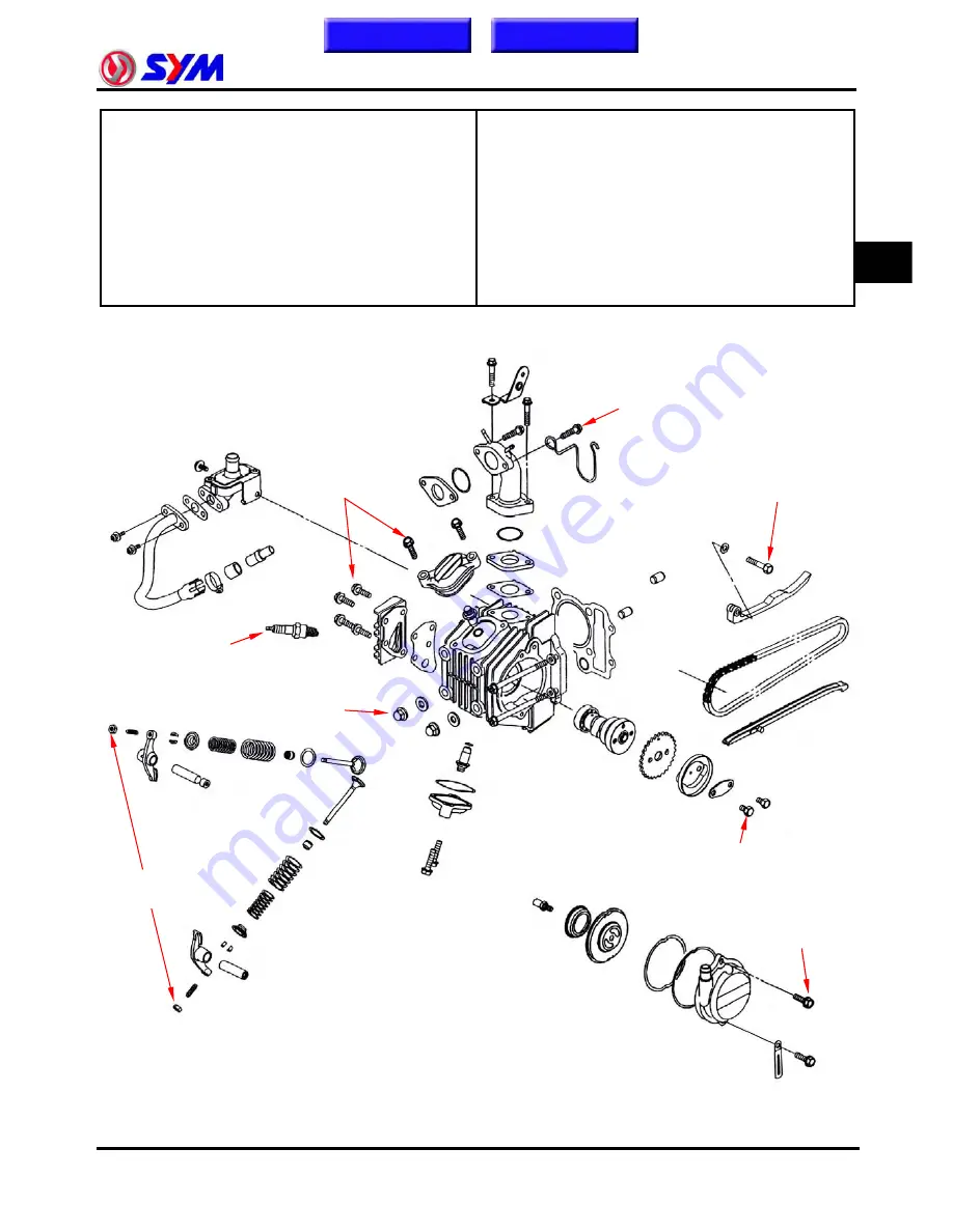
 

Mechanism Diagram


7


1.0~1.4kgf-m

0.7~1.1kgf-m 

0.8~1.2kgf-m

0.8~1.2kgf-m 

0.8~1.2kgf-m 

1.0~1.2kgf-m

1.0~1.2kgf-m 

1.0~1.2kgf-m 

Homepage

Contents 

Simpo PDF Merge and Split Unregistered Version - http://www.simpopdf.com

Summary of Contents for MB10A7-A series

Page 1: ...Symba 100 Service Manual FOREWORD CONTENTS HOW TO USE THIS MANUAL MECHANICAL LAYOUT Simpo PDF Merge and Split Unregistered Version http www simpopdf com...

Page 2: ...ction Adjustment providing technician with service guidelines Copyright reserved If the style and construction of the motorcycle MB10A7 A series motorcycle are different from that of the photos pictur...

Page 3: ...ick guide There are 4 buttons Foreword Contents How to Use This Manual and Mechanical Layout on the PDF version homepage and can access these items by clicking of the mouse If technician wants to see...

Page 4: ...Engine Removal 6 7 1 7 18 Cylinder Head Valve 7 8 1 8 10 Cylinder Piston 8 9 1 9 16 Crankshaft Crankcase Shifting Gear Kick Starter 9 10 1 10 20 Steering Front Wheel Front Suspension Front Brake 10 1...

Page 5: ...l Headlight Starting Switch Headlight Dimmer Winker Horn Switch Main Switch Taillight Fuel Tank Cap Rear Brake Pedal Battery Fuse CDI Regulator Rectifier Kick Starter RR Winker Ignition Coil Winker Re...

Page 6: ...cedures are not followed Engine oil Recommended oil Bramax motor oil or equivalent motor oil SAE 10W 30 API SH class oil Warranty will not cover the damage which is caused by not applying with the rec...

Page 7: ...n these parts wear insulated gloves and wait until the vehicle is cooling down Battery Caution Battery emits explosive gases flame is strictly prohibited Keeps the place well ventilated when charging...

Page 8: ...trol cable to prevent unsmooth control and premature worn out y Rubber parts may become deteriorated when old and easy to be damaged by solvent and oil Check these parts before installation to make su...

Page 9: ...me of the manufacturer facing outside and check the shaft on which the oil seal is to be installed for smoothness and for burrs that may damage the oil seal y Remove residues of the old gasket or seal...

Page 10: ...oid using tools like open end wrench which may contact with body or create spark y After service completed make sure all connection points is secured Battery positive cable should be connected firstly...

Page 11: ...ered by the twin connector boot completely and secured properly y Before terminal connection check if the boot is crack or the terminal is loose y Insert the terminal completely Check if the boot cove...

Page 12: ...tect wires or wire harnesses with electrical tape or tube if they contact a sharp edge or corner Thoroughly clean the surface where tape is to be applied y Secure the rubber boot firmly as applying it...

Page 13: ...fore operating a test instrument operator should read the operation manual of the instrument And then conduct test in accordance with the instruction y Use sand paper to clean connector pins terminals...

Page 14: ...oke gasoline engine Clutch Wet multi plate auto centrifugal clutch Installation and arrangement Vertical below center incline 15 Reduction Transmission 4 speed circulated Fuel Used Unleaded gasoline S...

Page 15: ...Cylinder head left bolt 1 6 0 8 1 2 7 8 12 Cylinder stud bolt 4 8 0 7 1 0 7 10 Cylinder head side cover bolt 3 6 0 8 1 2 7 8 12 Tappet adjustment hole cap 2 6 0 8 1 2 7 8 12 Tappet adjustment screw nu...

Page 16: ...procket nut 4 8 2 7 3 3 26 32 Front cushion mounting bolt 2 8 3 0 3 5 29 35 Rear cushion upper connection bolt 2 10 3 0 4 0 29 39 Rear cushion lower connection bolt 2 10 3 0 4 0 29 39 Brake lever nut...

Page 17: ...uel in fuel tank 2 Check if the pipes fuel tank to carburetor and intake vacuum are clogged 3 Float valve clogged 4 Lines in fuel tank evaporation system clogged 5 Malfunction of fuel pump 6 Loosen or...

Page 18: ...nes in fuel tank evaporation system clogged 3 Exhaust pipe clogged 4 Fuel level too low in carburetor 5 Fuel nozzle clogged in carburetor 1 Malfunction of CDI 2 Malfunction of AC alternator 1 Cylinder...

Page 19: ...ke gasket 4 Poor carburetor O ring 5 Vacuum hose crack 1 Spark plug fouled 2 Malfunction of CDI 3 Malfunction of AC generator 4 Malfunction of ignition coil 5 Open or short circuit in spark plug leads...

Page 20: ...cient fuel in fuel tank 2 Fuel filter clogged 3 Restricted fuel tank vent Good Poor Check and adjustment Fault condition Probable causes Check ignition timing 1 Malfunction of CDI 2 Malfunction of AC...

Page 21: ...motor to the battery 1 Bad contact in the starter switch 2 Abnormal Starter relay 3 Loose coupler or terminals Pull the brake handle or step on the braking pedal 1 Burnt Fuse 2 Insufficient Battery Vo...

Page 22: ...otor to the battery Starting Motor Still rotating slowly Rotates Normally Works smoothly Jammed 1 Loose coupler or terminals 2 Starting Relay bad contact 1 Engine Seized Kick the kick starter Turn the...

Page 23: ...the combustion chamber 3 Worn piston pin or connecting rod lower end Cam chain noise 1 Worn camshaft bearings 2 Worn cam sprocket 3 Loose or worn cam chain Clutch knocking 1 Excessive clutch plate cl...

Page 24: ...h wire Right winker wire Front brake switch wire Left handlebar switch wire Left winker wire Right handlebar switch wire Right winker wire Front brake switch wire Speedometer cable Throttle cable Fron...

Page 25: ...brake cable Wire harness couplers After clamp 1 is ready clamp all cable and wire harness Front left winker wire left handlebar switch wire headlight wire front right winker wire front brake light sw...

Page 26: ...gh wire grommet Push the wire clamp when the wires are at right place Throttle cable and main wire harness should be placed between the left air cleaner intake duct and the frame Main switch coupler l...

Page 27: ...y starter wire and main wire harness should be clamped properly AC Generator wire gear switch couplers should be packed well and clamped PCV drain pipe and carburetor drain pipe should go through the...

Page 28: ...nker wire should be clamped Fuel level gauge wire should be clamped Rear winker wire should be clamped Rear winker wire should go through winker stay hole To this chapter contents Simpo PDF Merge and...

Page 29: ...ts Throttle cable Front brake lever pivot Steering stem bearing Rear axle Main stand pivot Side stand pivot Speedometer pinion Front axle Drive chain To this chapter contents Simpo PDF Merge and Split...

Page 30: ...s Tightness 2 17 Special Tool Catalog 2 18 Precautions in Operation Specification Fuel Tank Capacity 4100 c c Capacity 1000 c c Engine Oil Changed 800 c c Throttle Cable Free Play 2 6 mm Spark Plug NG...

Page 31: ...ote I Inspection A Adjustment R Replacement C Clean L Lubrication Please have your periodical maintenance data recorded by your SYM Authorized Dealer to maintain the motorcycle in excellent condition...

Page 32: ...rm up the engine before drain oil that will make engine oil easily drained thoroughly Fill in the engine oil to the standard capacity Oil viscosity SAE 10W 30 Recommended using Bramax series engine oi...

Page 33: ...s strictly prohibited during operation z Fuel filter is sealed so cannot be cleaned Replace it if it s clogged If fuel filter is clogged please drain all the gasoline into a clean container and wash t...

Page 34: ...point solvent for example kerosene or diesel Squeeze out the cleaning solvent thoroughly soak the element into engine oil and squeeze out the excessive Re install the filter and the cover If the air...

Page 35: ...p through the inner side flange of it Free play 2 6 mm Please loosen the lock nut and adjust the throttle cable nut to reach the normal free play PCV System Unplug the drain pipe and leak the deposit...

Page 36: ...e inspection and adjustment Check the intake and exhaust valve clearance by inserting the feeler gauge between the adjusting screw and the lock nut Valve clearance IN EX 0 12 0 02 mm Adjust by looseni...

Page 37: ...nnect the tachometer onto engine 2 Turn the idle speed adjusting screw and let the engine run at the recommended idle speed 3 Insert the exhaust sampling pipe of exhaust analyzer into the front sectio...

Page 38: ...iming is incorrect check CDI set pulse rotor and pulse generator Replace defective parts if malfunction is found Idle Speed 1600 100rpm Ignition Advance 3300 100rpm Spark Plug Recommended spark plug C...

Page 39: ...reading in the gauge gains no more z Usually the highest pressure reading will appear in 4 7 seconds Compression pressure 11 1 Kg cm Check the following items if the pressure reading is too low z Inco...

Page 40: ...free play Turn the adjusting screw counterclockwise to decrease the free play of the gear change pedal Turn the adjusting screw clockwise to increase the free play After adjustment fix the adjusting...

Page 41: ...ndard range Caution y Turn the adjusting nuts of both sides evenly to make the drive chain and sprockets rotate smoothly Turn the nuts clockwise to tighten the chain or counterclockwise to loosen the...

Page 42: ...pension system will result in poor stability and maneuverability Front cushion Press down the front cushion for several times to check its integrity Check if any oil leaks or damage found Replace rela...

Page 43: ...adjusting nut to adjust the free play Turn the brake adjusting nut clockwise to decrease the free play Turn the nut counterclockwise to increase the free play Brake lining inspection When pressing th...

Page 44: ...8L Check the tire surface for embedded nails stones or other objects Check if front and rear tires pressure is normal If the wearing of the tire thread reaches triangle mark index the tire also have t...

Page 45: ...y impure water is filled in it will shorten the battery life Warning z The electrolyte contained sulfuric acid Please avoid touching the eyes skin or clothes If any contact by accident please flush wi...

Page 46: ...rter can be activated only under braking condition Rear brake switch adjustment Turn on the main switch When the brake pedal is stepped down for 20mm the brake lamp should be activated If the brake la...

Page 47: ...T ADJUSTING TOOLS Name ACG puller SY No SYM 9001200 SY No SYM 9001210 SY No SYM 3110A00 20 32 6 6203 6004UZ Name Special nut socket Name Oil seal driver Name Bearing driver SY No SYM 9023100 SY125 SY...

Page 48: ...Name Universal bearing driver SY No SYM 5320000 SY No SYM 5320020 SY No SYM 6204024 Name Inner bearing puller set Name Outer bearing puller Name Electrical gauge SY No SYM 6204020 SY No SYM 6204001 S...

Page 49: ...2 Maintenance Information 2 20 Note To this chapter contents Simpo PDF Merge and Split Unregistered Version http www simpopdf com...

Page 50: ...Valve 3 6 Float Chamber Jet Set 3 7 Carburetor Installation 3 10 Idle Speed Adjustment 3 11 Fuel Tank 3 12 Air Cleaner 3 14 0BMechanism Diagram Fuel gauge Fuel tank To vacuum tube Vacuum type fuel co...

Page 51: ...ion to O ring position replace with new one as re assembly z There is a drain screw in the float chamber for draining residual gasoline z Do not disassemble the auto by starter and air cut valve arbit...

Page 52: ...Impure fuel Misfire during acceleration z Malfunction of ignition system Late ignition timing z Malfunction of ignition system z Malfunction of carburetor Weak engine power z Fuel system clogged z Ma...

Page 53: ...away from fire and avoid getting on the frame If gasoline gets on the frame please wash it off immediately Disconnect the auto by starter coupler Disconnect the fuel pipe Disconnect the breather pipe...

Page 54: ...lts Remove the insulator and the carburetor Installation Install as the reversed order of removal procedures Torque value Carburetor holding nuts 0 7 1 1kgf m After installation the following adjustme...

Page 55: ...lockwise to remove the jet needle and the seat from the throttle valve Check the throttle valve and the jet needle to see if they are damaged or not Assembly Assemble as reversed order of removal proc...

Page 56: ...ction Check the float valve and valve seat for any damage or blocking Caution z In case of worn out or dirty the float valve and valve seat will not close tightly The fuel will overflow A worn out or...

Page 57: ...turn the adjusting screw forcefully or the valve seat may be damaged z When the air adjusting screw is removed take out the inner washer with it Clean the jets with Carburetor conditioner Then use co...

Page 58: ...w Caution Please assemble the air adjusting screw with the same setting circles as removal Assemble the main jet seat main jet and slow jet Assemble the float valve float and float pin Main jet Slow j...

Page 59: ...e main jet Fuel level 10 2mm Assemble the fuel cup after confirming the fuel level 6BCarburetor Installation Install the carburetor in the reverse order of removal Following adjustments must be made a...

Page 60: ...djust the throttle stopper screw of throttle valve to achieve the standard idle RPM Standard idle speed 1600rpm 100 Connect the hose of exhaust analyzer to exhaust front end Press test key on the anal...

Page 61: ...nkers and the rear fender 1 bolt 1 screw Remove the rear top cover Disconnect the fuel unit wire coupler Open the seat Disassemble the fuel vapor tube to the carbon canister 1 screw 2 bolts Wire coupl...

Page 62: ...e fuel tank cover Remove the lock bolts to separate the cover from the fuel tank Fuel unit removal Remove the fuel unit 3 screws Refer to the chapter 12 for the detailed inspection for the fuel unit F...

Page 63: ...e air filter element with non flammable or high flash point solvent Like kerosene or diesel After washing squeeze it and dump into motor oil and squeeze again If the element is too dirty or damaged pl...

Page 64: ...the air cleaner duct band and remove the air cleaner ducts both sides Remove the air cleaner 2 bolts on both sides Installation Install as the reversed order of removal 2 bolts on both sides 1 clamp F...

Page 65: ...3 Fuel System 3 16 Note To this chapter contents Simpo PDF Merge and Split Unregistered Version http www simpopdf com...

Page 66: ...m 4 Anti loose nut 3 8 4 5kgf m Clutch outer Primary drive gear Clutch weight Clutch spring Clutch set ring Clutch friction dick B Clutch plate A Clutch center Clutch outer cover Flexible washer Lock...

Page 67: ...rm return spring Gear shift arm pivot pin Shift drum stopper Shift drum stopper spring Shift drum pin Shift drum pin guide Shift drum plate Bearing 6805 Gear shift drum Shift fork Shift fork Shift for...

Page 68: ...nce between inner rotor and outer rotor 0 30 0 35 Clearance between outer rotor and the pump body 0 30 0 36 0 40 Oil pump Clearance between rotor and pump cover 0 0 06 0 11 Clutch pedal free play 10 2...

Page 69: ...Damaged cylinder head gasket y Worn piston ring Clutch slips during acceleration y Worn clutch plate y Weak clutch spring Bike trembles y Bent clutch plate Hard to shift gear y Improper y bent shift f...

Page 70: ...washer is damaged it should be replaced Torque value 1 5 2 5kgf m Oil Filter Screen Cleaning Remove the oil filter screen cover 2 bolts Remove the oil filter screen Clean the oil filter screen with c...

Page 71: ...ts Remove the clutch lift plate ball retainer and clutch cam plate spring Remove the clutch lever and clutch cam plate Remove the clutch outer cover 4 screws 8 bolts Clutch cam plate spring Clutch bal...

Page 72: ...clutch set ring Remove the drive gear outer clutch center clutch plates and clutch friction disks from the clutch outer Disassemble the drive gear outer clutch center clutch plates and clutch friction...

Page 73: ...the free length of four clutch springs Service limit 15 5mm Clutch friction disk inspection Measure the thickness of each clutch friction disk If it s under service limit or it s damaged replace it wi...

Page 74: ...o see if any cracks or damage can be found Clutch Installation Assemble the clutch drive plate onto the clutch outer 4 screws and install the clutch damper spring in the clutch outer Reinstall the clu...

Page 75: ...one location foot of the lock washer to fit in the locknut Install the clutch outer cover 4 screws Install the clutch cam plate Make the clutch lever aim at the breach of the clutch cam plate and ins...

Page 76: ...il Loosen the locknut of the clutch adjusting bolt Turn the clutch adjusting bolt counterclockwise to the end and then turn it clockwise 1 8 1 4 circle to adjust the clutch free play After the clutch...

Page 77: ...pe Remove the right crankcase cover Remove the clutch lever and the clutch assembly Remove the primary driven gear cir clip Remove the primary driven gear Remove the shift drum stopper and stopper spr...

Page 78: ...shift drum pins Remove the shift drum plate location pin and prevent it from being lost Inspection Check the gear shift spindle and gear shift arm for wear or damage Gear shift spindle Shift drum pin...

Page 79: ...drum cam for wear or damage Check the shift drum plate and shift drum pin for wear or damage Gear shift linkage mechanism assembly Install the shift drum plate location pin onto the gear shift drum Sh...

Page 80: ...bolt Torque value 0 8 1 2kgf m Caution z After the shift drum stopper is reinstalled make sure it operates well Install the primary driven gear and put on the cir clip Install the primary drive gear...

Page 81: ...pecial tool Special nut socket wrench SYM 9023100 SY125 Remove the oil pump 3 screws Caution z Impact screwdriver is allowed to be used to remove the oil pump lock screws Oil pump disassembly Remove t...

Page 82: ...the oil pump and outer rotor Service limit Under 0 35 mm Check the clearance between the inner and outer rotor Service limit Under 0 40mm Check the clearance between the surface of oil pump and rotor...

Page 83: ...stall the oil pump cover and washer 3 screws Torque value 0 3 0 4kgf m Caution z Make sure the oil pump rotate smoothly Install new o rings Install the oil pump driven gear location pin Install the oi...

Page 84: ...ear coordinate Install the primary drive gear Install the clutch assembly and clutch lever Install the location pin and new right crankcase cover gasket Install the right crankcase cover 8 bolts Torqu...

Page 85: ...4 Lubrication Clutch Transmission 4 20 Note To this chapter contents Simpo PDF Merge and Split Unregistered Version http www simpopdf com...

Page 86: ...5 6 Mechanism Diagram 5 1 0 1 4kgf m 0 8 1 2kgf m 3 5 4 3kgf m Homepage Contents Starter motor Flywheel ACG Stator Starter reduction gear shaft Starter reduction gear Starter clutch gear Starter clutc...

Page 87: ...pecification Measurement unit mm Item Service limit Starter clutch gear exterior diameter 35 91 Starter clutch outer interior diameter 37 8 Torque value Flywheel locknut 3 5 4 3kgf m Left crankcase co...

Page 88: ...the ACG coupler Disconnect the gear change switch coupler Remove the gear shift pedal 1 bolt Remove the left crankcase rear cover 2 bolts Remove the left crankcase cover 7 bolts Rubber cover 1 bolt 7...

Page 89: ...crews and ACG stator 2 bolts ACG stator inspection Check the following circuit for electricity conductivity White Green 0 7 10 Yellow Green 0 5 10 Black Red Green 780 10 Blue Yellow Green 110 10 2 scr...

Page 90: ...Assemble the stator wire correctly onto the left crankcase cover with the rubber seal Install the location pins and new left crankcase gasket Install the left crankcase cover 7 bolts Rubber seal 7 bol...

Page 91: ...uller Special tool ACG flywheel puller SYM 3110A00 Remove the starter clutch gear and needle bearing Remove the cir clip and starter reduction gear Remove the starter reduction gear shaft 2 screws Fly...

Page 92: ...r 12 96 mm Starter clutch inspection Install the starter clutch gear onto the starter clutch outer Hold the starter clutch and turn the starter clutch gear Make sure the starter clutch gear can only b...

Page 93: ...aps and springs Measure the inner diameter of the starter clutch outer Service limit Inner diameter under 37 8 mm Assembly Assemble in the reversed process of disassembly Caution z Apply some screw ad...

Page 94: ...e starter reduction gear and cir clip Install the ACG flywheel starter clutch and starter clutch gear 1 locknut Torque value 5 0 6 0kgf m Install the location pins and new gasket onto the crankcase 2...

Page 95: ...e left crankcase cover with the rubber seal Install the left crankcase cover 7 bolts Torque value 1 5 2 0kgf m Install the left crankcase rear cover 2 bolts 7 bolts Rubber seal 2 bolts To this chapter...

Page 96: ...4 Clutch 5 Gear shift mechanism 6 Cylinder Piston 7 Cam chain tensioner 8 Cam shaft Rocker arm You must remove the engine for repairing the following parts 1 Crankshaft 2 Gear box 3 Kick starter mecha...

Page 97: ...ositive pole Remove the battery 2 bolts Caution z To prevent short circuit always connect the positive pole before the negative one Remove the starter motor power cable Remove the AICV pipe Engine oil...

Page 98: ...clamp Remove the step bar 4 bolts Remove the exhaust pipe 3 locknuts Disconnect the ACG wire and gear change switch 2 locknuts ACG wire and gear h it h Spark plug cap Cord clamp 4 bolts 1 locknut To t...

Page 99: ...nut and push the rear wheel forward Remove the left crankcase rear cover Remove the driving sprocket holding bolts Turn slightly and take out the stopping plate then remove the driving sprocket and ch...

Page 100: ...ables can t be bent or pressed z Please align the wires and cables in accordance with the setting diagram Torque value Engine locknut rear part of engine and frame 3 0 3 5kgf m Step bar lock bolt 2 4...

Page 101: ...6 Engine Removal 6 6 Note To this chapter contents Simpo PDF Merge and Split Unregistered Version http www simpopdf com...

Page 102: ...Valve 7 8 Valve Seat Inspection Refacing 7 12 Cylinder Head Assembly 7 15 Cylinder Head Installation 7 16 Valve Clearance Adjustment 7 18 Mechanism Diagram 7 1 0 1 4kgf m 0 7 1 1kgf m 0 8 1 2kgf m 0 8...

Page 103: ...0 055 0 100 Valve seat width 1 200 1 600 Inner spring 32 500 30 500 Valve Valve spring free length Outer spring 34 750 34 000 Warp clearance between cylinder head and cylinder 0 050 Torque valve Cyli...

Page 104: ...ug not tightened of badly assembled 2 Cylinder head Cylinder head gasket leaking or damage Tilt or crack cylinder 3 Piston Worn piston rings High compression pressure Too much carbon deposit on combus...

Page 105: ...3 locknuts Remove the PCV breather pipe and the cylinder head left side cover 2 bolts Remove the timing inspecting hole cap and ACG cap Rotate the crankshaft counterclockwise to match the TDC mark T...

Page 106: ...n sprocket 2 bolts Caution z After removing the cam chain sprocket drag out the cam chain to prevent it from falling into the crankcase Remove the cylinder head left side lock bolt 6mm 2 bolts 2 bolts...

Page 107: ...faces of cylinder and cylinder head Caution z Don t damage the matching surfaces of cylinder and cylinder head z Avoid residues of gasket or foreign materials falling into crankcase when cleaning 4 lo...

Page 108: ...r SYM 1445100 Remove the valve rocker arm Camshaft Camshaft removal Use a 5mm bolt or the rocker arm shaft camshaft puller to pull out the camshaft Special tool Rocker arm shaft camshaft puller SYM 14...

Page 109: ...e limit 10 1mm Valve rocker arm shaft inspection Check the valve rocker arm shaft outer diameter for wear Valve rocker arm shaft outer diameter service limit 9 90mm Valve Valve removal Clean the carbo...

Page 110: ...ssemble tool SYM 1471110 20 Caution z To avoid damaging the valve stem and the cylinder head put a rag under the cylinder head when compressing the valve spring Cylinder head inspection Clean the gask...

Page 111: ...er diameter of valve guide deducts the outer diameter of valve stem is the clearance value between the valve stem and valve guide Service Limit Intake 0 08mm Exhaust 0 10mm Caution z If clearance is o...

Page 112: ...valve guide cylinder head still have to be maintained 100 150 Adjust the valve guide driver and let valve guide height be 13 mm Press in new valve guide from rocker arm side Tool Valve guide driver 5m...

Page 113: ...If the valve is burned worn or its contact face is uneven replace it z If the valve contacts the seat unevenly after grinding replace it Check the valve seat contact condition If the valve seat is too...

Page 114: ...e valve seat Caution z Reface the valve seat with 45 degree valve seat cutter after removing the valve guide Use the 32 degree cutter to remove the upper 1 4 part of the valve seat Use the 60 degree c...

Page 115: ...valve seat with 32 cutter Then grind the valve seat to specified width If the contact surface too low grind the valve seat with 60 cutter Then grind the valve seat to specified width After grinding t...

Page 116: ...ly wound coils face the combustion chamber Tap the valve stem slightly with rubber hammer to make valve cotters and valve stem match perfectly Caution z Place and hold cylinder head on to working tabl...

Page 117: ...head locknuts more than standard torque value or the cylinder head may be deformed making abnormal noise leakage and decreasing the performance Tighten the cylinder head left side lock bolt 6mm Torque...

Page 118: ...sprocket with that of cylinder head Tighten the sprocket mounting bolts Torque value 1 0 1 2kgf m Install the cylinder head side cover 2 bolts Torque value 0 8 1 2kgf m Install the tappet adjusting ho...

Page 119: ...r the valve clearance being adjusted to standard value hold adjustment bolt and then tighten the locknut Valve clearance 0 12 0 02 mm Caution z Make sure the valve clearance be adjusted to the standar...

Page 120: ...2 Troubleshooting 8 2 Cylinder Removal Inspection 8 3 Piston Removal Inspection 8 5 Piston Rings Installation 8 8 Piston Installation 8 9 Cylinder Installation 8 10 Mechanism Diagram 8 Homepage Conten...

Page 121: ...cond piston ring Piston cylinder clearance 0 020 0 050 0 110 Piston Piston rings Piston pin hole inner diameter 15 002 15 008 15 050 Piston pin outer diameter 14 994 15 000 14 950 Piston piston pin cl...

Page 122: ...e crankcase when removing the cylinder Remove the cylinder gasket dowel pins and o ring Clean all the gasket material from the sealing surface Caution z Use solvent to wet the gasket material in order...

Page 123: ...t of round at three levels in X and Y axis Take the maximum value to determine the cylinder wear Service limit Out of round 0 05 mm Taper 0 05 mm Check the top of the cylinder for warp Service limit 0...

Page 124: ...move the piston rings Caution z Pay attention when removing the piston rings because they are fragile Check if the piston rings are damaged or its grooves are worn Clean out the carbon deposit from th...

Page 125: ...imit Top ring 0 5 mm Second ring 0 5 mm Measure the piston pin outer diameter Service limit 14 95 mm Measure the inner diameter of connecting rod small end Service limit 15 05 mm Measure the inner dia...

Page 126: ...ton outer diameter 90 degrees to the piston pin hole Service limit 52 25 mm Calculate the clearance between the piston and cylinder Measure the piston ring thickness Service limit 0 90 mm To this chap...

Page 127: ...z Do not damage the piston and piston rings during installation z All marks on the piston rings must face up side z Make sure that all piston rings can be rotated freely after installation Top groove...

Page 128: ...ly Assemble the piston and piston pin and place the IN mark on the piston top side forward to inlet valve Assemble the new piston pin clip Caution z Do not let the opening of piston pin clip align wit...

Page 129: ...he piston rings in one by one as installation Caution z Do not push the piston into cylinder forcefully or the piston and piston rings could be damaged Install the cam chain guide dowel pins and cylin...

Page 130: ...pection 9 12 Crankcase Assembly 9 13 Mechanism Diagram Crankcase Crankshaft Kick starter 9 0 8 1 2kgf m Kick starter pinion Oil seal 12x22x9 Oil seal 17x30x7 Bearing TMB304CS10 Bearing 6007C2 Bearing...

Page 131: ...rum stopper Shift drum stopper spring Shift drum pin Drum lock plate Shift drum plate Bearing 6805 Gear indication drill Gear shift spindle Gear shift arm Gear shift return spring Gear shift arm stopp...

Page 132: ...dard Service limit Connecting rod big end side clearance 0 050 0 300 0 600 Connecting rod big end vertical clearance 0 004 0 012 0 050 Run out 0 100 Crankshaft Connecting rod small end inner diameter...

Page 133: ...n pin or piston pin hole Hard to shift gear z Bent shift fork z Bent shift fork shaft z Bent shift fork claw Transmission jumps out of gear z Worn gear teeth z Bent or damaged shift fork z Bent shift...

Page 134: ...1 bolt Remove the cam chain Remove the gear change switch 2 screws Remove the gear indication drill and spring in advance to avoid losing them Remove the lock bolts from the left crankcase 2 screws 7...

Page 135: ...emove the shift fork shafts Remove the main shaft and counter shaft shift forks Remove the gear shift drum Remove the main gear shaft and counter gear shaft Shift fork shaft Shift fork shaft Gear shif...

Page 136: ...e limit 0 6 mm Measure the clearance of the big end at the vertical directions Service limit 0 05 mm Place the crankshaft on a V block measure run out of the crankshaft Service limit 0 10 mm Measure t...

Page 137: ...xcessive noise or roughness Left crankcase bearing 6007C2 Right crankcase bearing TMB304CS10 Shifting Gear Inspection Check if the gear shift fork is worn bent or damaged Measure the inner diameter of...

Page 138: ...f the gear for wear and damage Assemble the gears and washers onto the main shaft and counter shaft by order after the inspection is finished without anything incorrect Caution z Apply clean engine oi...

Page 139: ...e starter drive ratchet and spring Remove the spindle collar kick starter spring and thrust washer Remove the kick starter pinion Measure the inner diameter of the kick starter pinion Service limit 20...

Page 140: ...er Put the kick starter stopper on the left crankcase Rotate the kick starter spindle counterclockwise by using kick starter arm to make the drive ratchet turn over the kick starter stopper Push down...

Page 141: ...ughness Check the oil seal of the counter shaft for any damage replace it with new one if necessary Transmission bearing removal Remove the damaged bearing by using the inner bearing puller Special to...

Page 142: ...Install the main shaft shift fork make the shift fork guide in the upper shift drum guide groove and install the shift fork shaft Install the counter shaft shift fork make the shift fork guide in the...

Page 143: ...se Tighten the locknuts on the left crankcase Torque value 0 8 1 2kgf m Apply some grease to the oil seal of the counter shaft and then knock the oil seal in slightly Install the gear indication drill...

Page 144: ...ankshaft Crankcase Shifting Gear Kick Starter 9 15 Install the cam chain and cam chain set plate 1 bolt 1 bolt To this chapter contents Simpo PDF Merge and Split Unregistered Version http www simpopdf...

Page 145: ...9 Crankshaft Crankcase Shifting Gear Kick Starter 9 16 Note To this chapter contents Simpo PDF Merge and Split Unregistered Version http www simpopdf com...

Page 146: ...peedometer 10 5 Handlebar 10 6 Front Wheel 10 9 Front Suspension 10 13 Steering Stem 10 16 Front Brake Hub 10 19 Front Brake Shoes 10 19 Front Brake Panel 10 20 Mechanism Diagram 4 0 5 0kgf m 0 15 0 2...

Page 147: ...unit mm Item Standard Service limit Axle run out 0 2 Axial 2 0 Wheel rim run out Radial 2 0 Front brake drum inner diameter 110 00 111 00 Front brake lining thickness 4mm 2mm Torque value Front axle l...

Page 148: ...pe z Too much cushion fluid Front suspension noise z Bent cushion pipe z Insufficient cushion fluid z Loose cushion fastener Drum brake Weak brake z Incorrect brake adjustment z Worn brake shoe z Worn...

Page 149: ...adlight Installation Align the headlight location mark and install the headlight Install other parts in reverse order Headlight angle adjustment Loosen the headlight lock bolt and adjust the headlight...

Page 150: ...wire coupler Remove the speedometer cover 3 screws Remove the speedometer cover stay 2 bolts Remove the speedometer cable and the speedometer Installation Install in the reverse order Speedometer cab...

Page 151: ...r Remove the back mirror headlight and speedometer Remove the handle wire band Remove the front brake lever pivot locknut Remove the front brake lever Loosen the throttle cable locknut Remove the righ...

Page 152: ...ve the left handle switch 2 screws Remove the handle pipe up holder bolt caps Remove the handle pipe up holder 4 bolts Remove the handle pipe Bolt caps 4 bolts 2 screws To this chapter contents Simpo...

Page 153: ...grease to the sliding surface Align the raised point inside the handle switch with the location hole on the steering handle pipe After assembling the handle pipe set confirm and adjust the following y...

Page 154: ...brake panel Remove the brake cable Remove the front wheel axle locknut Pull out the front wheel axle Remove the front wheel brake panel and side collar Inspection Front wheel axle Put the axle on a V...

Page 155: ...tor Service limit Radial 2 0mm Axial 2 0mm Disassembly Pull out the left bearing by using inner bearing puller Remove the front axle distance collar Pull out the right bearing and oil seal by using in...

Page 156: ...on Align the raised parts of the speedometer gear receiver with the grooves of the front wheel hub Install the front brake panel Caution z Contaminated brake shoe will decrease braking efficiency ther...

Page 157: ...n Assemble the front wheel axle locknut and lock it to the specified torque value Torque value 4 0 5 0kgf m Assemble the speedometer cable to the brake panel Install the front brake cable Axle locknut...

Page 158: ...e upper lock bolt on the front fender A Separate the front fender A and front fender B Remove the front inner fender and front fender B 3 bolts Release the front cushion bolts and front cushion upper...

Page 159: ...il seal Pour out the cushion oil Remove the oil seal stopper ring and then remove the old oil seal Caution y Do not damage the fork pipe when removing the oil seal Coat the inner side of the new oil s...

Page 160: ...pipe by hand and lock the fork bolt as tight as possible Lock the fork lock bolts Torque value 3 0 3 5kgf m Lock the fork bolt again Install the front inner fender and front fender B 3 bolts Assemble...

Page 161: ...SYM 5320000 Upper cone race wrench SYM 5320020 Remove the steering stem Remove the steering steel balls from the steering upper bottom ball race Upper steering steel ball number 26 Bottom steering ste...

Page 162: ...m and lubricate with grease Install the steering upper bottom ball race to the right position Caution y Do not let the ball race lean on one side during installation Coat the upper bottom ball race wi...

Page 163: ...one race or the steering ball race may be damaged Fix the steering upper cone race and tighten the steering stem locknut Special tool Steering stem locknut socket wrench SYM 5320000 Steering upper con...

Page 164: ...ction Check if the wheel hub is damaged or worn out Replace the wheel hub if necessary Measure the inner diameter of the wheel hub Service limit 111 0mm Caution z Rub the wheel hub with 120 sandpaper...

Page 165: ...the brake shoe is contaminated by grease braking efficiency will decrease or even totally lose Front Brake Panel Brake panel removal Remove the front brake arm lock bolt Remove the brake arm brake ca...

Page 166: ...wheel hub 110 0 111 0 Drive chain slack 10 20 Brake lining thickness 4 0 2 0 Torque value Rear axle locknut 5 0 6 0kgf m Final driven flange locknut 6 0 7 0kgf m Final driven sprocket lock bolt 2 7 3...

Page 167: ...heel hub z Worn brake cam z Incorrect brake shoe installation z Jammed or interfered brake pedal z Contaminated brake lining z Contaminated wheel hub z Brake shoe brake cam contact face worn out z Imp...

Page 168: ...nuts Remove the rear fork axle locknut Remove the exhaust pipe Remove the rear brake torque link 1 locknut Remove the brake adjusting nut and rear brake rod 2 mounting nuts 1 locknut Brake adjusting...

Page 169: ...ar drive chain adjusters and rear brake penal Caution z Inhaling asbestos may cause disorders of respiration system or cancer therefore never use air hose or dry brush to clean brake parts Use vacuum...

Page 170: ...smoothly or quietly replace it with new one Caution z The old bearing cannot be reused but be replaced with new one by pairs Rim Place the rim in a rotating stand Spin the rim by hand and measure the...

Page 171: ...with 120 sandpaper if it is rusty z Measure the inner diameter of the wheel hub by a vernier caliper Brake shoes Measure the brake lining thickness on three points 2 ends and the middle If the brake...

Page 172: ...alue 5 0 6 0kgf m Fix the rear wheel axle and tighten the rear axle locknut Torque value 6 0 7 0kgf m Tighten the adjuster nut slightly to prevent it from loosening Install the rear brake torque link...

Page 173: ...rear cover 2 bolts Remove the drive sprocket lock bolts Remove the drive sprocket fixing plate and drive sprocket Remove the drive chain upper lower covers 4 bolts Remove the drive chain fixing clip...

Page 174: ...eaning Check the drive chain for wear or damage Replace it if necessary Driven flange driven sprocket removal Remove the rear wheel and drive chain Remove the rear wheel axle locknut and final driven...

Page 175: ...and the raised parts for crack or damage Bearing inspection Turn the inner ring of each bearing to check if it rotates smoothly and quietly Meanwhile check if the outer ring fits the wheel hub closely...

Page 176: ...e driven sprocket and rear axle sleeve to the rear fork Install the left side drive chain adjuster and lock the final driven flange by hand Install the rear wheel rear axle distance collar and right s...

Page 177: ...flange locknut 6 0 7 0kgf m After locking the rear wheel axle locknut tighten the drive chain adjuster nuts slightly to prevent the adjuster nuts from being loosened Check the drive chain slack again...

Page 178: ...Rear cushion locknut 3 0 4 0kgf m Caution z Rear cushion should be replaced as a complete set z Rubber bush and structure will be damaged during disassembly Press the rear cushion to check if the rear...

Page 179: ...ive chain final driven sprocket drive chain cases and rear cushions Remove the rear brake torque link Pull out the rear fork pivot bolt Remove the rear fork Inspection Check the rear fork for wear or...

Page 180: ...he rear fork rubber bush Special tool Rubber bush puller driver SYM 1120310 Press in the new rear fork rubber bush Special tool Rubber bush puller driver SYM 1120310 Apply grease to the both sides of...

Page 181: ...Remove the rear brake pedal spring Hold the vehicle with a hanger Remove the split pin of the rear brake pivot bolt Pull out the rear brake pivot bolt Remove the rear brake pedal and main stand Insta...

Page 182: ...stem 12 16 Switch Horn 12 21 Fuel Unit 12 25 Mechanism Diagram Spark plug Winker relay AC Generator Resistor Tool bag Ignition coil Main switch Fuel unit Winker Horn switch Starter Light Front stop sw...

Page 183: ...later check if the terminal voltage is over 12 5V or not Recharge the battery if the terminal voltage is too low Charging the new battery before using it may lengthen the battery life span Follow the...

Page 184: ...m Control voltage in charging 14 3 0 5V Fuse 7A Ignition system Item Specification Type NGK C6HSA Spark plug Clearance 0 6 0 7 mm Primary winding 1 2 15 Secondary winding with cap 10 7 K 15 Ignition c...

Page 185: ...or ignition coil Poor contact of cable Poor contact of main switch z Secondary winding circuit Poor ignition coil Poor spark plug Poor ignition coil cable Current leakage from spark plug cap z Incorre...

Page 186: ...Fully charged 1 220 Insufficiently charged Caution z Recharge the battery when the specific gravity of electrolyte is below 1 23 z The specific gravity of electrolyte changes when the temperature chan...

Page 187: ...g z Before or after charging always turn off the charging machine to avoid explosion caused by sparks z Follow the regulated charging current and time shown on the battery Caution z Do not charge the...

Page 188: ...voltage Charging current Over 1 5A 2500rpm Over 1 8A 5000rpm Charging control voltage 14 3 0 5V 2100rpm Caution z Check if the charging current voltage is normal or not after replacing new battery Th...

Page 189: ...scale then gradually decrease to the lower scale as the test process goes to avoid possible damage to the ammeter and the fuse z Do not turn on the main switch when testing the current leakage If the...

Page 190: ...h green frame grounding Close circuit Charge coil white earth green Close circuit with resistance Lamp coil yellow earth green Close circuit with resistance ACG Regulator rectifier Fuse 7A Battery Bro...

Page 191: ...ed value would be affected AC Generator coil inspection Caution z The inspection of AC Generator charge coil lamp coil can be proceeded on the engine Measure the resistor value between AC Generator wi...

Page 192: ...6K 15 without cap 20 C 10 7K 15 with cap 20 C Exciter coil inspection Disconnect the AC Generator 6 pin coupler Measure the resistance between the terminal Black Red and terminal Green Standard value...

Page 193: ...lowing terminals from the wire side Item Check points Standard value 20 C Main switch Black White Green Close circuit when OFF Exciter coil Black Red Green 780 20 Pulse coil Blue Yellow Green 110 20 P...

Page 194: ...plug cap Disconnect the ignition coil primary winding wire black yellow and green Remove the ignition coil 2 locknuts Install in the reverse order of removal Use a multi meter with input resistor ove...

Page 195: ...an ohmmeter to the starter relay terminal Connect the yellow red wire to the battery positive terminal and the green yellow wire to the battery negative terminal Check the continuity of the starter re...

Page 196: ...between the battery negative terminal and starter motor case Check the starter motor rotating condition Replace the starter motor if the rotating speed is too slow Starter motor installation Install i...

Page 197: ...ker Right winker indicator Left winker indicator Winker switch Winker relay Taillight Meter light Gear switch Blue Gray Orange Pink Black Yellow Green White Light green red Sky blue Black License ligh...

Page 198: ...h the headlight lens Tighten the lock screw Make sure the headlight work properly Adjust the headlight beam Headlight beam adjustment Loosen the headlight lock bolt and move the headlight up and down...

Page 199: ...out the bulb and replace it if necessary Specification Winker bulb 12V 10W Installation Install in the reverse order of removal Winker bulb can also be replaced with the reflector be pulled out Cauti...

Page 200: ...e carrier 2 bolts Remove the winker lock bolts and disconnect the wire coupler Remove the right left winker Remove the license plate bracket 2 bolts Remove the lock bolt and screw on the rear fender 1...

Page 201: ...nuts Specification Taillight Brake light 12V LED Caution z Taillight Brake light are LED type it needs to be replaced as a set Installation Install in the reverse order of removal Coupler 2 locknuts T...

Page 202: ...Red Black B W Green Replacement Remove the main switch cover and front cover protector Remove the front cover 6 bolts Disconnect the main switch wire coupler Remove the main switch brocket 3 bolts Re...

Page 203: ...or Yellow Red Green Removal Loosen the throttle cable locknut remove the lock screws Remove the throttle cable and disassemble the right handle switch Installation Assemble in the reverse order of dis...

Page 204: ...rn switch HO BAT FREE Wire color Light green Green Removal Remove the lock screws and disassemble the left handle switch Installation Assemble in the reverse order of disassembly Make sure the switch...

Page 205: ...e coupler and remove the horn 1 bolt Remove the front cover and front under spoiler Apply 12 V power source to two terminals of the horn the horn should make sound Replace the horn if necessary Adjust...

Page 206: ...eter as shown Connect the fuel unit coupler to the wire harness Turn on the main switch Move the float arm to verify the proper position the fuel gauge needle indicates Float arm position LED display...

Page 207: ...12 Electrical System 12 26 Note To this chapter contents Simpo PDF Merge and Split Unregistered Version http www simpopdf com...

Page 208: ...ing intake and exhaust timing have all contributed to maximize the intake exhaust efficiency and combustion efficiency Secondary air introducing system It is used to introduce secondary air into exhau...

Page 209: ...into engine together with air from bottom of the canister The canister can be used repeatedly without reducing its performance because of the system s purge function 3 Trouble Diagnosis Fuel can not f...

Page 210: ...ge should not drop to below 10mmAq within 10 seconds 3 PCV Function Test 1 Disconnect the hose of connection to the active carbon canister and then connect a T type hose connector to pressure source a...

Page 211: ...nsfer unburned CO HC and NOx harmless CO2 H2O N2 gases 2 Pt Pd Rh etc precious metals are used into the catalytic converter so use only unleaded gasoline to prevent from cause the catalytic converter...

Page 212: ...the exhaust manifold is negative reed valve will be sucked open by the negative pressure and outside air will enter to mix with CO HC thus generating a secondary burn reaction and turning them into h...

Page 213: ...vice methods a Visual check y Check reed valve air cut off valve secondary air cleaner for outside damages y Check metal pipes and hoses for breakage and cracks b Leak test y Plug the hose leading to...

Page 214: ...age y If there is no vacuum replace reed valve and test again y If there is no vacuum check the air pipe for leakage plugged or loose Secondary air inject filter Air injection cut valve Reed valve Cyl...

Page 215: ...e separated vapor will be sucked into combustion chamber by engine negative pressure to be burned again instead of discharging into atmosphere Drain liquidized fuel in the drain pipe periodically 3 Se...

Page 216: ...oid Catalytic converter 1 Check if exhaust gas content is within standard 2 Remove the exhaust pipe and shake it gently for noise Fuel Supply System 1 Clean the air filter 2 Check the air filter 3 Cle...

Page 217: ...ication after adjusted the carburetor then clean or replace it with new one according to the procedures Conduct periodical inspection check one time for 1500 km 6 months Test exhaust contents at idlin...

Page 218: ...14 Electrical Diagram 14 1 14 Symba100 Homepage Contents Simpo PDF Merge and Split Unregistered Version http www simpopdf com...

Page 219: ...14 Electrical Diagram 14 2 Note Homepage Contents Simpo PDF Merge and Split Unregistered Version http www simpopdf com...

Reviews: