


6
Supplied Accessories
Owner’s Manual
Quick Start Guide
Installation
EN
Installation
FR
Instalación
ES
If you have any questions, please visit our website at
www.
sylvaniaconsumerelectronics.com
Quick
Start
Registration card
Remote
Control
(NH210 UD)
Batteries
(AAA, 1.5V x 2)
AAA
AAA
TV base and 6 screws (M5 x 12)
AC power cord
Note
• If you lose the screws, please purchase (M5 x 12) Phillips head
screws at your local store.
• If you need to replace these accessories, please refer to the part
name or No. with the illustrations and call our toll free customer
support line found on the cover of this manual.
When using a universal remote control to operate this unit.
• Make sure the component code on your universal remote control
is set to our brand. Refer to the manual accompanying your
remote control for more details.
• We do not guarantee 100% interoperability with all universal
remote controls.
Symbols Used in this Manual
The following is the description for the symbols used in this
manual. Description refers to:
ATSC
: Digital TV operation
NTSC
: Analog / Cable TV operation
• If neither symbol appears, the operation is applicable to
both.
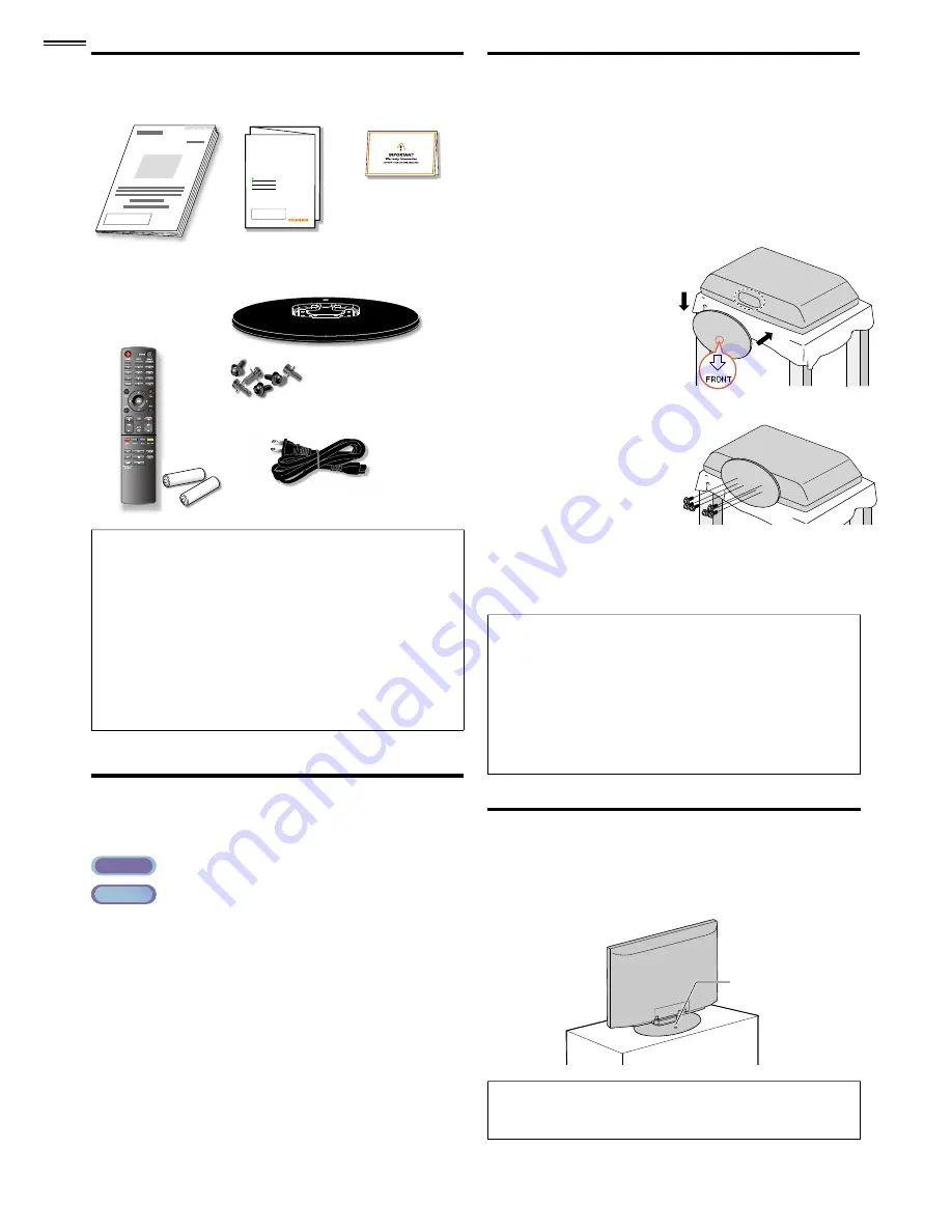
Attaching the Base
You must attach the base to the unit to have it as a table top
unit. Be sure the front and rear of the base match the proper
direction. At least 2 people are required for these steps.
.
1
Check the text “FRONT” with “arrow“ on the Base’s
bottom to ensure it is being installed in the correct
direction. Spread a thick and soft cloth over a table as shown
at step
2
. Place the main unit face down onto it. Make sure
not to damage the screen.
2
Insert 2 hooks under the
bottom of the main unit
into base holes (shown by
arrow
➀
), then move the
➀
base in the direction as
shown by arrow
➁
until
➁
it stops and the screw
holes are aligned.
➁
➀
3
Drive Phillips head screws
into the 6 threaded holes
at the bottom of the base
until they are tight.
To remove the base from this unit
• Unscrew the Phillips head screws in step
3
.
After the screws are removed, pull the base up toward the rear of
r
the unit. Be careful not to drop the base when you remove it.
Note
• When attaching the base, ensure that all screws are tightly fastened.
If the base is not properly attached, it could cause the unit to fall,
resulting in injuries as well as damage to the unit.
• Make sure to use a table which can support the weight of this unit
and is larger than this unit.
• Make sure the table is in a stable location.
• When attaching the base, ensure that “FRONT” with “arrow”
written on the bottom of the base is downward. If it’s not
downward , the 2 hooks don’t
fi
t into the base.
Mounting the Unit on Your Furniture
Screw this unit on your furniture tightly using wood screw (not
supplied) in the hole at the back of the base as shown.
• Recommended screw dimension : 3/16 x 3/4 inches (5.1 x 20 mm)
screw hole
screw hole
rear of this unit
rear of this unit
Note
• When you remove this unit make sure to unscrew the wood
screw from your Wood Stand, Furniture and other wood item.


