Page 10
For example, a Raptor using an asymmetric Narrow Beam A2 reflector type (with a B=60°
offset) that requires a tilt of 66
0
should have the glass tilted 66-60=6
°
. Tilts can be negative.
Method 2 – with aiming device
1.
Place markers, (visible from floodlight), at reference points according to lighting design.
2.
Slightly loosen/tighten the torque on the trunnion bracket bolt so the floodlight can be
rotated while the weight is still held securely.
3.
Unclip the plastic bolt head caps from the two side adjustment bolts (if necessary). Slightly
loosen/tighten the torque on the side bolts (19mm) so the floodlight can be tilted while the
weight is still held securely.
4.
Loosen either one of the side bolts by a few turns sufficiently to remove the blank ring, and
attach the supplied aiming sight (Fig 4). The aiming sight has a reference mark, and teeth at
5° spacing. It needs to be inserted so the mark aligns with the reference direction angle A°
(where A=90-B, Fig 2). For example, a Raptor using an asymmetric Narrow Beam A2 reflector
type (with a B=60° offset), A=90-60=30° (Fig 5). For a symmetric reflector angle B will be 0° so
that angle A=90°.
5.
Re-tighten the torque on the side bolt so the floodlight can be tilted while the weight is still
held securely.
6.
Using the v-notch and post sight on the aiming device aim to the applicable marker (Fig 4).
The sight ring can be left in place.
7.
Tighten the trunnion bracket mounting bolt to the required torque (by others) so that
floodlight will no longer rotate.
8.
The azimuth angle can be marked for future reference by marking a line in the cross arm
along the back and/or front of the trunnion bracket foot (without damaging galvanising).
9.
Tighten side bolts (19mm) so that the floodlight will no longer tilt (110 nm).
10.
Tighten the safety side screws (5mm Hex - 10 nm).
11.
The tilt angle can be marked for future reference by writing in the box provided on the type
label near the side bolt.
12.
Clip on the plastic bolt covers.
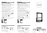
Fig 2
Fig 3


