


1-7-6
TD709EA
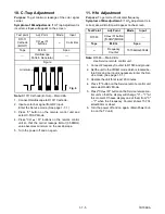
12. Y DL Time/Y SW LPF
Adjustment
Purpose: To get minimum leakage of the color signal
carrier.
Symptom of Misadjustment: If Y DL Time Adjust-
ment is incorrect, stripes will appear on the screen.
1. Enter the Service Mode. (See page 1-7-1.)
2. Y DL Time Adjustment: Press "0" button on the
service remote control unit twice to show "D-T" on
the display.
Y SW LPF Adjustment: Press "0" button on the
service remote control unit four times to show
"Y SW" on the display.
3. Y DL Time Adjustment: Select "2" by pressing
"CH
o
/
p
" buttons on the service remote control
to enter Y DL Time Adjustment mode.
Y SW LPF Adjustment: Select "0" by pressing
"CH
o
/
p
" buttons on the service remote control
to enter Y SW LPF Adjustment mode.
4. If needed, perform the following.
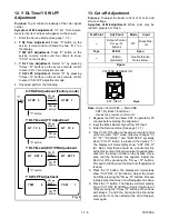
13. Cut-off Adjustment
Purpose: To adjust the beam current of R, G, B, and
screen voltage.
Symptom of Misadjustment: White color may be
reddish, greenish or bluish.
Note: Screen Control FBT --- Main CBA
FBT= Fly Back Transformer
Use service remote control unit
1. Degauss the CRT and allow CRT to operate for 20
minutes before starting the alignment.
2. Input the Black Raster Signal from RF Input.
3. Enter the Service mode. (See page 1-7-1)
4. Press "VOL
p
" button on the service remote control
unit and select "C/D" mode. (Display changes "C/
D," "7F," "DVD-KEY," and "DVD-TEST" cyclically
when "VOL
p
" button is pressed.) then press "1."
The display will momentarily show "CUT OFF R"
(R= Red.) Now there should be a horizontal line
across the center of the picture tube. If needed grad-
ually turn the screen control on the flyback, clock-
wise until the horizontal line appears. Adjust the
Red Cut off by pressing the "CH
o
/
p
" buttons.
Proceed to Step 5 when the Red Cut off adjustment
is done.
5. Press the "2" button. The display will momentarily
show "CUT OFF G" (G=Green.) Adjust the Green
Cut off by pressing the "CH
o
/
p
" buttons. Proceed
to step 6 when the Green Cut off adjustment is done.
6. Press the "3" button. The display will momentarily
show "CUT OFF B" (B=Blue.) Adjust the Blue cut
off by pressing the "CH
o
/
p
" buttons. When done
with steps 4, 5 and 6 the horizontal line should be
pure white if not, then attempt the Cut off adjust-
ment again.
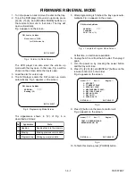
Y DL Time Adj TV Adjustment
CH
button
D-T TV 0
D-T TV 2
button
CH
Y DL Time Adj EXT/PB Adjustment
CH
button
D-T EXT 0
D-T EXT 2
button
CH
"0" button
Y SW LPF Adjustment
CH
button
Y SW
button
CH
"0" button
"0"
button
C-TRAP Adjustment (Factory mode)
CH
button
C-TRP 0
C-TRP 1
button
CH
"0" button
0
Y SW
1
Fig. 5
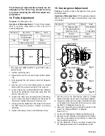
Test Point
Adj. Point
Mode
Input
---
Screen-Control
CH
o
/
p
buttons
RF
Black Ras-
ter
Tape
M. EQ.
Spec.
---
Pattern
Generator
See Reference
Notes below.
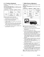
Figure
PATTERN GENERATOR
Fig. 6
EXT. INPUT