background image

6

ENGAGING BLADES
Note: 
Do not attempt to start the unit with the T-handle console in the “ENGAGED” position.
• Engage blades by pulling down the T-handle lever into the horizontal position.
• Return lever to the vertical position to disengage blades. See Fig 8 pg 16.
•The braking system is applied when the blades become disengaged. It is designed to bring the blades

to a quick stop (approximately 7 seconds).  Each Trail Cutter brake system has been set at the factory    
the consumer should not alter any part of the brake system.

BREAKING IN YOUR CUTTER

Set the vehicle parking brake and chock the wheels to prevent accidental rolling.

While the engine is running, slowly engage blade control.

In a safe environment, (i.e. no children or pets) allow blades to rotate and engine to

idle for 5 minutes, breaking in the belt for a longer life.

Stop cutter.

FRONT TO BACK ADJUSTMENT
For best cutting results, the cutter deck should be parallel to the ground.  To check parallel adjustment, 
measure the distance from the bottom edge of the deck in both the front and rear of the deck.  This 
adjustment is best done while the tow vehicle and Trail Cutter are connected.

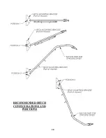
Remove hair pins NB127 from clevis pins 18842 so L-hitch 18829 can be repositioned.

Raise or lower hitch section to obtain proper front to back adjustment.

Insert clevis pins in the desired hitch position and secure with hair pins.

CAUTION:  SHUT OFF THE CUTTER ENGINE AND REMOVE SPARK 
PLUG WIRE FROM SPARK PLUG BEFORE MAKING ANY 
ADJUSTMENTS TO THE CUTTER.

STARTING THE ENGINE

See engine manufacturer’s recommendations for the type and amount of oil and fuel used. Trail Cutters 
equipped with an electric start engine will need a battery (sold separately).  Swisher recommends using a 
standard “U1” battery. 

Make sure the tow vehicle parking brake is set, mower is level, and blades are

disengaged. Engine must be level to accurately check and fill oil. Do not overfill.

Check spark plug wire, oil, and fuel.

Check all electrical connections for buildup of debris.

Set engine idle to “CHOKE” position.

Turn key to the “RUN” position.

Pull rope with a single fluid motion.

(12V models only) Turn key to the “RUN” position, then to the “START” position.

Set engine idle at maximum RPM for best performance.

Allow engine to run a few moments before engaging blades.

IMPORTANT: This engine is not equipped with a spark arrester muffler. It is a violation of 
California Public Resource Code Section 4442 to use or operate the engine on any forest-covered, 
brush-covered, or grass-covered land. Other states or federal areas may have similar laws. 

Summary of Contents for QBRC14544

Page 1: ...Manufacturing quality lawn care equipment since 1945 Assembly Operation Service and Adjustment Repair Parts MODEL NO STARTING SERIAL L113 335001 QBRC11544 QBRC14544 QBRC14544 CA 17341 REV 13 335 Impo...

Page 2: ...h the instructions contained within this manual This warranty does not apply to any product of Swisher that has been subject to alteration misuse abuse improper assembly or installation shipping damag...

Page 3: ...setting up transporting adjusting or making repairs Keep all shields and guards in place Understand the speed steering and stability of this machine Know the positions and operations of all controls...

Page 4: ...stop approximately 7 seconds Each Trail Cutter brake system has been set at the factory For safety the consumer should not alter the braking system 4 ASSEMBLY Disengage spark plug wire and place where...

Page 5: ...er should be towed behind an ATV golf cart lawn tractor or other approved vehicle It is not recommended for speeds exceeding 5 MPH ATTACHING TRAIL CUTTER TO TOW VEHICLE Back vehicle up to desired towi...

Page 6: ...is pins 18842 so L hitch 18829 can be repositioned Raise or lower hitch section to obtain proper front to back adjustment Insert clevis pins in the desired hitch position and secure with hair pins CAU...

Page 7: ...ig 8 pg 16 Carefully mount tow vehicle and start mowing at a slow travel speed STOPPING THE CUTTING SESSION Bring tow vehicle to a complete stop set the parking brake and disengage blades Turn key swi...

Page 8: ...Y MAINTENANCE Make sure all nuts and bolts are tight and cotter pins and retainer springs are secure Keep blades sharp Observe all safety precautions BLADE CARE AND SERVICE For best results cutter bla...

Page 9: ...trical connections and inspect spark plug and wire Contact engine manufacturer or qualified mechanic Engine runs poorly See engine manual Check the throttle adjuster Replace fuel clean fuel filter and...

Page 10: ...rt number from Swisher 1 800 222 8183 8 5 CT M F OD82 44 RUGGED CUT DECAL OD29 DANGER DECAL 19976 SWISHER FLAG DECAL OD33 5MPH DECAL OD36 DEFLECTOR DECAL OD55 DANGER DECAL OD45 WARNING DECAL OD10 ENGA...

Page 11: ...0 14GA Sq Tube 18834 2 Pin Safety Hitch 3 8 X 2 1 2 H11 3 Weldment L Hitch 18829 4 Washer SAE Flat 3 8 NB272 5 Bolt 3 8 16 X 3 NB150 6 Nut Nyloc 3 8 16 NB182 7 Tube Hitch Elbow 18833 8 Pin Hair 39 NB1...

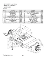
Page 12: ...1 15 Weldment Axle Bar Right 10356 FIGURE 3 MOTOR BASE WHEEL HEIGHT ADJUSTMENT ASSEMBLIES 12 When ordering replacement parts USE PAINT CODE TK BLACK Item Description Part 16 Washer Nylon 1 4 NB194 17...

Page 13: ...Gusset Right 15057 6 Z Bracket Jack Support 15055 7 Front Rail Deck Support 15054 8 Remote Cable Mount Bolt On 15059 9 Bracket Remote Cable Detent 15606 10 Rail RT44 Right 17358 11 Weldment Blade Moun...

Page 14: ...iver Housing 4858 10 Bolt 1 2 13 X 2 NB509 11 Washer 1 X 1 1 2 X 10GA NB614HT 12 Nut Nyloc 3 4 10 NB609 13 Weldment Stump Jumper 4859 14 Blade 10358 15 Washer 3 4 X 1 1 4 X 18GA NB179 16 Bolt 3 4 10 X...

Page 15: ...3 8 16 X 2 1 2 HTC GR5 ZP NB619 21 Washer Belleville 699 22 3 8 16 Nyloc Nut NB182 23 1 4 20 HX Nut ZP NB139 24 Brake Rod 4891 25 5 16 18 X 1 HCC GR5 ZP NB501 26 Spacer B99S 27 5 16 18 Nyloc Nut NB18...

Page 16: ...console weldment 4575 on top of the hitch tube and assemble the console mount plate 4852 from underneath the hitch tube using the hardware provided Make sure the wiring harness is secure and will not...

Page 17: ...WIRING DIAGRAM 11 5HP ENGINE FIGURE 9 17 WIRING DIAGRAM 14 5HP ENGINE FIGURE 10 10299 19193...

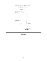
Page 18: ...Notes 18 FIGURE 11 ENGINE TO BLADE PULLEY CONFIGURATION P N B527 P N 4846 P N BB105 P N BA50...

Page 19: ...Tek 1 4 X 3 4 NB161 18 Battery Pad BATPAD Not Shown Battery Cable Black 10 BCS Not Shown Battery Cable 10 Red BCSR Not Shown Battery Cable Small Rubber Boot BCBT REPAIR PARTS Your 44 Trailcutter has b...

Page 20: ...RECOMMENDED HITCH CONFIGURATIONS AND POSITIONS 20...

Page 21: ...21...

Page 22: ..._________________________________________________________________ ______________________________________________________________________ _______________________________________________________________...

Page 23: ..._________________________________________________________________ ______________________________________________________________________ _______________________________________________________________...

Page 24: ...may be ordered from the nearest dealer of the engine supplied with your mower WHEN ORDERING PARTS PLEASE HAVE THE FOLLOWING INFORMATION AVAILABLE PRODUCT FC44 TRAIL CUTTER SERIAL NUMBER ______________...

Reviews: