Swegon GOLD SD 004 Operation & Maintenance Instructions Manual Download Page 16

GB.GOLDSKFSD.190515

We reserve the right to alter specifications.

16     www.swegon.com

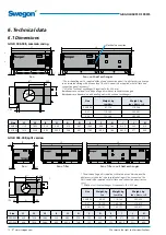
6.2 Connection to Wiring Terminals

SD

WLAN

CPU 1

CPU 2

1

A

2

B

3

GND

4

+

5

-

6

+

7

-

8

+

9

-

10

+

11

-

12

+

13

-

SA Temp

Com 5

Com 4

Com 3

Com 2

Com 1

14

+

15

-

16

+

17

-

18

+

19

-

Heat

Cool

20

C

21

NO

22

C

23

NO

24

C

25

NO

26

C

27

NO

28

P

29

G

30

G0

31

G

32

G0

24V AC

Sensor 1 Sensor 2

Sensor 4

Sensor 3

Com 6

Com 7

Com 8

Com 9

Com 10 Com 11

+

33

-

34

G

35

G0

36

Y

37

U

38

39 40

24V AC In

41 42

18V AC In

45 46

230V AC In

47

43 44

230V AC Out

Digital inputs, terminals 4-17, are of extra-low voltage type. Analogue input, terminals 18-19 have an input impedance of 66 k

Ω

.

230 VAC control voltage is on external terminals 101 (L) and 102 (N).

Wiring 
terminal

Function

Remarks

1,2,3

Connections for EIA -485

1= Communication connection A/RT+, 2= Communication connection B/RT–, 3= GND/COM.

4,5

External stop

Stops the unit by opening the circuit. On delivery, this function is fitted with a jumper. If the connec-
tion is interrupted, the unit will stop.

6,7

External fire/smoke function 1

External fire and smoke function. On delivery, this function is fitted with a jumper. If the connection is 
interrupted, the function will trip and initiate an alarm.

8,9

External fire/smoke function 2

External fire and smoke function. On delivery, this function is fitted with a jumper. If the connection is 
interrupted, the function will trip and initiate an alarm.

10,11

External alarm 1

External contact function. Optional: Normally open/normally closed. 

12,13

External alarm 2

External contact function. Optional: Normally open/normally closed. 

14,15

External low speed

External contact function. Oversteers the timer from stop to low speed operation.

16,17

External high speed

External contact function. Oversteers the timer from stop or low speed to high speed operation.

18,19

Demand control

Input for 0-10 V DC. The input signal influences the supply air/extract airflow set point if the unit is 
operating in the demand control mode. For connection of sensors, for example CO

2

, CO and VOC

20,21

Circulation pump, heating circuit

Independent contact, max. 5 A/AC1, 2 A/AC3, 250 VAC. Closes on a heating load.

22,23

Circulation pump, cooling circuit or 
cooling on/off, 1-step operation

Independent contact, max. 5 A/AC1, 2 A/AC3, 250 VAC. Closes on a cooling load.

24,25

Cooling, on/off, 2-step operation

Independent contact, max. 5 A/AC1, 2 A/AC3, 250 VAC. Closes on a cooling load.

26,27

In-operation indication

Independent contact, max. 5 A/AC1, 2 A/AC3, 250 VAC. Closes when the unit is operating.

28,29,30

Damper control

24 VAC. 28= Controlled 24 VAC (G), 29= 24 VAC (G), 30= 24 VAC (G0). 

31,32

Control voltage 

1)

24 VAC control voltage. Terminals 31-32 are loaded with a total of 16 VA. Opened by means of the 
safety isolating switch.

33,34

Reference voltage

Output for constant 10 VDC. Max. permissible load: 8 mA.

35,36,37,38 Control, recirculation damper

The recirculation damper can be loaded with max. 2 mA at 10 VDC. 35= 24 V AC (G), 36= 24 V AC (G0), 
37= 0-10 V DC control signal, 38= 0-10 VDC feedback signal.

The max permissible common load on terminals 31-32, outputs for Heat/Cool and damper output (terminals 28-30) is max 32 VA (SD) eller 50 VA (RX/PX/CX).

1)

 GOLD 100/120: If more than 16 VA is required, use wiring terminals 201 (G) and 202 (G0). Terminals 201-202 can be loaded with a total of max, 48 VA.

The max. permissible load on the correspond-
ing connection is 16 VA.

Glass fuse, 3.15A

Summary of Contents for GOLD SD 004

Page 1: ...OPERATION MAINTENANCE INSTRUCTIONS GOLD SD Generation F ...

Page 2: ... 4 Maintenance 9 4 1 Filter change 9 4 1 1 Dismantling the filters 9 4 1 2 Installing new filters 9 4 2 Cleaning and Inspection 10 4 2 1 General 10 4 2 2 Filter spaces 10 4 2 3 Heat exchangers 10 4 2 4 Fans and fan spaces 10 4 3 Service and Functionality Check 11 4 4 Warranty 11 5 Alarms and Troubleshooting 11 5 1 General 11 5 1 1 A and B Alarms 11 5 1 2 To Reset Alarms 11 5 1 3 To Change Alarm Pr...

Page 3: ...e instructions have not been followed correctly Warning Only a qualified electrician or service personnel trained by Swegon shall be permitted to carry out any work on the electrical system or wire external functions in the air handling unit 1 1 Safety Isolating Switch Main Switch On sizes 004 080 the safety isolating switch is located on the inspection side by the inspection door of the fan secti...

Page 4: ...and carefully follow the installation instructions provided in each paragraph The product identification plates are located on the inspection side of the air handling unit and on a wall inside the fan section Refer to the particulars on the product identification plate when you contact Swegon 2 3 Mechanical Design The GOLD is available in 9 physical sizes and for 18 airflow ranges The outer sheet ...

Page 5: ...ct Not used in extract air units 5 SUPPLY AIR In extract air units Exhaust air 6 Coil heat exchanger supply air if applicable In extract air units Coil heat exchanger extract air 7 Sensor Outdoor temperature For air handling units with coil heat exchanger only For extract air units Extract air temperature relative humid ity sensor 8 Supply air fan with motor and motor controller In extract air han...

Page 6: ...ounted in supply air duct Not used in extract air units 5 SUPPLY AIR In extract air units Exhaust air 6 Supply air fan with motor and motor controller In extract air handling units Extract air fan with motor and motor controller 7 Pressure sensor supply air fan Position on function selector switch 2 In extract air units Pressure sensor extract air fan 8 Electrical equipm cubicle with control unit ...

Page 7: ...n Program the time switch operating mode temperatures airflows and functions according to the procedures in Section 4 in the Function Manual Installation Select whether the airflow unit of measurement shall be l s m3 s m3 h or cfm Fill out the Commissioning Record and save it in the docu ment pocket of the air handling unit In some cases it might be necessary to adjust the P band and the I time if...

Page 8: ... should be fully open throttle the others to the same quotient Adjust the air devices in branch duct A The index air device here is air device A3 which means that you first throttle air device A4 the reference device to device A3 s quotient Then adjust the others to the same quo tient as air device A4 Throttle branch damper B to the same quotient as branch damper A throttle branch damper C to the ...

Page 9: ...tandard filters Pull out the handles A to free the filters from the filter holder Withdraw the filters Possible pre filters inside the air handling unit Withdraw the filters 4 1 2 Installing new filters Standard filters Insert the filters into the filter holder At the same time draw out the filter bags if installed so that they will not become caught damaged or folded Insert the filters as far as ...

Page 10: ... clean with water Always clean against the regular direction of airflow Cleaning must only be done by blowing with compressed air vacuum cleaning with a soft nozzle or wet cleaning with water and or solvent Before you begin cleaning cover adjacent func tional sections to protect them If cleaning solvent is used do not use solvent that will corrode aluminium or copper Swegon s cleaning agent is rec...

Page 11: ...an also be reset via a communication network not applicable to frost guard alarm 5 1 3 To Change Alarm Priority See Section 4 8 6 in the Function Manual Installation 4 4 Warranty To submit a warranty claim you must be able to produce a com plete documented and signed Service and Functionality Inspec tion Report of the product with hits accessories A Service and Functionality Inspection Report must...

Page 12: ...lied with full face end connection panel acces sory Width of coil heat exchanger if required B 200 mm GOLD 004 008 split version F G 14 14 52 52 SD J E D 52 52 SD L1 L2 F G 14 52 52 45 45 A SD B 200 I 11 H J E 52 SD L1 L2 H 100 Ø Electrical connection Size L1 L2 B H A D E F G I J Ø 004 005 1120 1955 825 460 579 887 1068 956 164 412 5 230 315 007 008 1214 2049 995 542 5 749 887 1162 1050 164 497 5 ...

Page 13: ... I 11 SD SD H 100 45 45 A J 52 52 52 52 Ø L1 F G 158 16 L2 E D 16 200 11 SD SD 45 J 52 52 52 52 Fan Fan coil heat exchanger 52 52 SD SD SD 45 200 11 J J L1 16 16 L2 E C L3 E D C Size Weight kg fan Weight kg fan filter Weight kg fan filter coil 011 109 138 184 222 368 412 012 120 149 195 233 379 423 Size L1 L2 L3 B H A C D E I J Ø 011 012 878 1598 2433 1199 647 5 953 828 835 772 599 5 324 400 Fan F...

Page 14: ...39 5 Fan Fan filter Fan filter coil heat exchanger If the duct accessoy is housed in an insulated casing the AHU is sup plied without end connec tioin panel the AHU can also be supplied with full face end connection panel accessory Width of coil heat ex changer if applicable B 200 mm 0 H 52 52 SD SD SD L1 F 154 21 21 L2 E C L3 E D C Size Weight kg fan Weight kg fan filter Weight kg fan filter coil...

Page 15: ...56 B G O N 180 200 N I I C E D L3 SD 21 F H J J 100 45 3186 77 122 1048 1000 1048 77 56 21 190 M E K L1 K C L2 56 N 180 200 I C E D L3 C SD SD 21 F H J J 100 77 56 Size Weight kg section for power connection fan Weight kg filter section for power conn fan Weight kg filter coil fan 100 861 937 1263 1477 2133 2372 120 961 1046 1363 1586 2233 2481 Size L1 L2 L3 B H C D E F G I J K M N O 100 120 1681 ...

Page 16: ...ow speed External contact function Oversteers the timer from stop to low speed operation 16 17 External high speed External contact function Oversteers the timer from stop or low speed to high speed operation 18 19 Demand control Input for 0 10 V DC The input signal influences the supply air extract airflow set point if the unit is operating in the demand control mode For connection of sensors for...

Page 17: ...nt 2 3 phase 5 wire 400 V 10 15 50 Hz 63 AT 6 3 2 Fans RATED DATA PER FAN GOLD 004 Motor shaft power 0 8 kW 0 41 kW motor controller 1 x 230 V 50 Hz GOLD 005 Motor shaft power 0 8 kW motor control system 1 x 230 V 50 Hz or Motor shaft power 1 15 kW motor controller 1 x 230 V 50 Hz GOLD 007 Motor shaft power 0 8 kW motor control system 1 x 230 V 50 Hz or Motor shaft power 1 15 kW motor controller 1...

Page 18: ...80 A FUSES IN THE ELECTRICAL EQUIPMENT CUBICLE 230 V control current All the sizes variants One 2 pole 6A automatic circuit breaker Fans GOLD 004 007 GOLD 008 cap var 1 GOLD 011 cap var 1 SD One 2 pole 10A automatic circuit breaker GOLD 008 cap var 2 GOLD 011 cap var 2 GOLD 012 014 GOLD 020 cap var 1 SD One 6 3A protective motor switch GOLD 020 cap var 2 SD One 7 0A protective motor switch GOLD 02...

Page 19: ...61000 3 12 provided that the short circuit power Ssc is greater than or equal to the value in the table below for each size capacity variant It is the duty of the installer or user of the equipment to ensure through consultation with the distribution network operator if necessary that the equipment is only connected to a supply with the correct short circuit power Ssc for each unit GOLD SD size ca...

Page 20: ...f machinery General principles for design Risk assessment and risk mitigation EN 60204 1 2006 Safety of machinery Electrical equipment of machines Part 1 Generic standards EN ISO 13857 2008 Safety of machinery Safety distances to prevent hazard zones from being reached by arms and legs EN 61000 6 2 2005 Electromagnetic compatibility EMC Part 6 2 Generic standards Immunity for industrial environmen...

Page 21: ...tware Foundation either version 3 of the License or at your option any later version This program is distributed in the hope that it will be useful but WITHOUT ANY WARRANTY without even the implied warranty of MERCHANTABILITY or FITNESS FOR A PARTICULAR PURPOSE See the GNU General Public License for more details You should have received a copy of the GNU General Public License along with this prog...

Page 22: ...GB GOLDSKFSD 190515 We reserve the right to alter specifications 22 www swegon com All documentation is available in digital form and can be downloaded from www swegon com ...

Reviews: