


R9-H | R15-H
Smart
14
All rights to changes reserved.
2020-11-12
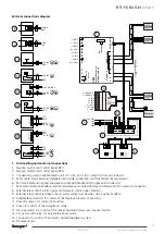
4.4 Relay outputs
External devices or systems can be controlled with relay
control outputs (+ 24 VDC). The units two inputs (IO1
and IO2) can control external relays. SEM* module has
one inbuilt relay (IO3) and two outputs for external relays
(IO4 and IO5). IO5 is grounding digital output for direct
connection to automation system.
Installation
Install external relay or system according to drawings.
NOTE! The control card can be damaged if you short-
circuit the IO connection selected by the relay output.
Settings
Relay settings can be changed in
Settings
/
(1234)/IO con-
trols
menu. Configure input type to
relay output
. Select
active state according to application.
Closed
selection
will close/activate the relay output when function is
active (NO).
Operations
Select required relay function:
1. Damper
Output is active when unit is running.
2. Away
Output is active when unit is in Away mode.
3. Boost
Output is active when unit is in Boost mode.
4. Modbus
Output is controlled with Modbus.
5. DI control
Output is controlled with digital input. Switch input
must be defined as relay control. Relay output mini-
mum and/or maximum active time can be defined
from IO controls menu.
6. Manual on
Output is always on.
7. Travelling
Output is active when unit is in Travelling mode.
8. Service
.
Output is active when service reminder is active.
9. Critical alarm
Output is active when critical alarm is active. Unit is
operating in restricted mode.
10. Alarm
Output is active when any alarm is active.
4.5 Voltage outputs (AO)
External devices or systems can be controlled with analog
output (0...10 V). SEM/SEC* module has one analog
output (AO4).
Installation
Install device or control cable to AO4 and ground.
Settings
IO settings can be changed in
Settings
/
(1234)/IO con-
trols/AO4
menu.
Operations
Select required output function:
1. Operating mode
Operating mode output 0...10 VDC
0 V = NA
1 V = Travelling
2 V = Away
5 V = Home
8 V = Boost
10 V = Stopped
2. Operating mode, stepless
Operating mode output 0...10 VDC
0 V = Control disabled
1 V = Travelling
2 V = Away
Stepless output between Away and Home
5 V = Home
Stepless output between Home and Boost
8 V = Boost
10 V = Stopped
3. Temperature setpoint
Temperature setpoint (10-30
°
C) corresponds to 0...10 V.
4. Modbus
Output is controlled with Modbus.
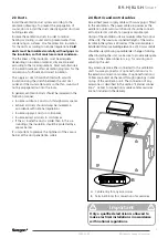
4.6 Smart Access
Unit can be controlled, monitored and commissioned
with web service Smart Access*. Smart Access allows
automatic alarm and service notifications through email.
Smart Access provides unit specified links to spare parts
and filter web shop and to Casahelp.
Installation
Install Smart Access device cable to unit internal con-
nector or connect cable to SEC/SEM (Modbus and IO4).
Connect Smart Access to public internet with ethernet
cable (ETH connector).
Settings
If Smart Access is connected to internal connector no
settings are required.
If Smart Access is connected to SEC/SEM module select
Smart Access enabled in
Settings
/
(1234)/Modbus
menu.
Operations
Read the QR code from Smart Access device with smart
device and follow the instructions.
*) Accessory
Smart Access:
More information
Summary of Contents for CASA R15H Smart
Page 9: ...9 R9 H R15 H Smart All rights to changes reserved 2020 11 12...
Page 21: ...21 R9 H R15 H Smart All rights to changes reserved 2020 11 12...
Page 34: ...R9 H R15 H Smart 34 All rights to changes reserved 2020 11 12...
Page 35: ...35 R9 H R15 H Smart All rights to changes reserved 2020 11 12...


