Swegon ADAPT Free d Installation, Commissioning Maintenance Download Page 4

4

Swegon reserves the right to alter specifications. 

20151013 

www.swegon.com

WISE

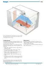
Figure 7. Wiring of Master/Slave air diffusers and accessories.

1.   ADAPT Master air diffuser 
2.   ADAPT Slave air diffusers 
3.   CONNECT Adapt, connection box 
4.   24 V AC Transformer 
5.   LINK Adapt (5 m long RJ45 cable) 
6.   LINK Modbus (5 m long RJ12 cable) 
7a.  TUNE Temp (1 VA) 
7b.  DETECT Quality (Room version with display - Q0: 1 VA.  
 

Room version without display Q1 and duct version - Q2: 3 VA) 

7c.  DETECT RH, humidity sensor (1 VA) 
8.   ACTUATOR, radiator control (max 3 valves at 6 VA) 
9.   ADAPT Relay, relay for lighting 
10.  Connection to main control system (Modbus RTU) 
11.  SPLIT Link RJ45 
12.  SPLIT Modbus RJ12, max. stab length, 10 m.

*) 

Only one of the accessories in paragraph 7 can be connected at 

any one time in a room installation.

  20

Master

  21

Slave

  22

Slave

   23

Modbus

 1    2    3   4    5    6    7    8    9  10  11  12  13  14  15  16 

6

5

4

3

9

5

5

10

-  + C

A1  A2 


1   3

1

2

2

2

11

5

12

6

8

5

1

6

7a

7b

G

G0

OUT1

1

2

3

7c

6

6

12

12

Summary of Contents for ADAPT Free d

Page 1: ...n figure 4 the frontplate of the diffuser must be dismantled and rotated in a direction with the sensor module directed as shown in figure 2 Then fixate and secure the diffuser with screws or pop rivets Readjust the hanger rods of the commissioning box if necessary 3 The front plate is dismantled by pressing the fixing pins of the bottom plate outward which will loosen it from the upper cone Detac...

Page 2: ...es orange The different LED indications Steady green LED Normal operation the air diffuser is operating normally Flashing green LED The air diffuser has just been powered on and calibration is in progress Steady red LED Function failure see separate docu mentation inte the TUNE Adapt manual Steady orange LED The commissioning mode max airflow Flashing orange LED Other commissioning modes and all t...

Page 3: ...f longer distances are required All cables and contacts are different so that they will not be confused or incorrectly connected Electrical data ADAPT is supplied with power via the connection box See the wiring diagram in figure 7 or relevant diagram from the Swegon Templates application containing details for the specific installation It is important that cables with appro priate cross sectional...

Page 4: ... with display Q0 1 VA Room version without display Q1 and duct version Q2 3 VA 7c DETECT RH humidity sensor 1 VA 8 ACTUATOR radiator control max 3 valves at 6 VA 9 ADAPT Relay relay for lighting 10 Connection to main control system Modbus RTU 11 SPLIT Link RJ45 12 SPLIT Modbus RJ12 max stab length 10 m Only one of the accessories in paragraph 7 can be connected at any one time in a room installati...

Reviews: