background image

PTC2: (seven byte)

PTC3: (seven byte)

Byte 5 and byte 6 are ransom value from 0x00 to 0xff.
Byte 7 = mod [(byte2 + byte3 + byte4 + byte5 + byte6)/100]
Note: This protocol is the same as PELCO-D, which is used to control a speed dome. So, if 
you use PELCO-D to control a speed dome with your keyboard, you can also use the 
keyboard to control the DVR through this protocol using a different address to distinguish the 
DVR and the speed dome.

Byte1  Byte2


Byte3


Byt4


Byte5


Byte6


Byte7


0xFF 

Addr 

Var1  Var2 


Check 

sum 


Var1 

Var2 

Function 

PELCO-D 

0x00 

0x08


Ch1/up 

Up 

0x00


0x10


Ch2/down


Down 

0x00


0x04


Ch3/left


Left 

0x00


0x02


Ch4/right


Right 

0x04


0x00


Chall/enter 

Iris close 

0x00


0x40


Record 

Zoom 

wide 

0x00


0x20


Play 

zoom tele 

0x02


0x00


Search 

Iris open 

0x00


0x80


WM/+ 

Focus far 

0x01 

0x00 

Display/- 

Focus 

near 


Transmitting S.N 

Transmitting 

worth 

Instructions 

Byte1 

0x03 

Fixed byte 

Byte2 

0xaa 

DVR identifier word 

Byte3 

0x01 

Fixed byte 

Byte4 

Device id 

DVR device address 

Byte5~7 

Refer to PTC 1  

Same command as PTC 1  
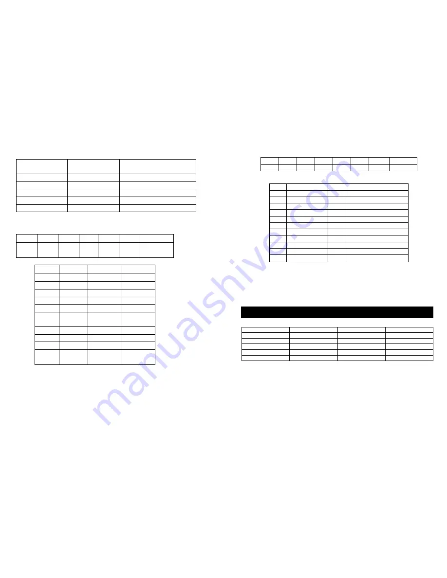
 

PTC4: (eight byte)

Note: This protocol is the same as PELCO-P's call function; you can use PELCO-P's call 
function to control the DVR. First, you must set right protocol, baud rate and address, second, 
you push the call button on the keypad, then enter the number according to the 

Var

 table 

above, then push the enter button.

Note: The above figures are from our test results using a default setup, and are for the users 
reference. Actual recording times may vary depending on hard disk size, subject complexity, 
camera resolution and movement within the frame.

Byte1  Byte2  Byte3  Byte4  Byte5  Byte6  Byte7 

Byte8 

0xa0 

Addr 

0x00 

0x07 

0x00 

Var 

0xAF 

Checksum 

         Byte8 = byte1 xor byte2 xor byte3 xor byte4 xor byte5 xor byte6 xor byte7  
 

Var 

Function 

Var 

Function 

0x01 

Ch1/up 

0x0C 

Schedule 

0x02 

Ch2/down 

0x0D 

0/next field 

0x03 

Ch3/left 

0x0E 

1/auto 

0x04 

Ch4/right 

0x0F 

2/zoom 

0x05 

Chall/enter 

0x10 

3/PIP 

0x06 

record 

0x11 

4/trip 

0x07 

Play 

0x12 

5/stop 

0x08 

Pause 

0x13 

6/search 

0x09 

Reward 

0x14 

7/WM/add 

0x0A 

Forward 

0x15 

8/display/DEC 

0x0B 

Menu 

0x16 

9/previous field 


Rec rate field/sec 

Picture quality 

Resolution 

Recording time 

50 fps 

Very high 

720 

7.5 hours 

50 fps 

Low 

720 

20 hours 

25 fps 

Normal 

360 

24 hours 

25 fps 

Low 

360 

67 hours 

1 fps 

Normal 

720 

720 hours 


Appendix C: record time for 40GB hard disk (hours) 

Summary of Contents for DIGITAL GUARDIAN DVR4-NET

Page 1: ...etup 7 8 Name Setup 7 9 Br Con Setup 8 10 Record Setup 8 11 Network Setup 9 12 N Enable Set 10 13 Mac Set 11 14 Alarm Setup 11 15 Motion Detection Settings 12 16 Area Set 13 17 Schedule Set 13 18 Protocol Set 14 Buttons On the Front Panel 14 1 Recording Playing Control Buttons Area 1 2 Function Control Area 15 3 Channel Choosing Control Area 16 Display Status While Running 17 1 Screen Display Whil...

Page 2: ...DVR4Net to avoid excessive heat Do not install the DVR near a radiator ventilating trunk heat sources under direct sunshine dusty locations or anywhere there is a chance for mechanical vibration or impact Video input 4channels video output 2 channels Audio input 4channels audio output 1 channels Four optional levels of image quality very high high normal low Record and playback frame rate change e...

Page 3: ...elds e g year month day hour minute second etc push the left button or right button to move to the different digits of one field continuous pushing will make it move among digits one by one and it can recur Please push the or button to change the value that the cursor shows then push the ENTER button to enter the sub menu and push Menu button to return to previous menu 2 Accessing the Menu If the ...

Page 4: ...the System Setup confirmation window will appear which is illustrated below If you select YES and push the enter button all video on the HDD will be deleted if you do not want delete all recordings please select NO 6 Factory Reset When the cursor moves to Factory Reset please push enter button the confirmation window will appear which is illustrated as below If you select YES and push the enter bu...

Page 5: ...not access to this menu unless you stop record or play first OVER WRITE if set to YES the DVR will automatically overwrite the HDD from the beginning when the HDD is full If set to NO the DVR will automatically stop recording when the HDD is full REC SPEED the recording frame rate of the DVR factory default setting is 30F 1SEC for NTSC 25F 1SEC for PAL Which means DVR records the events at the spe...

Page 6: ... Network SPEED If the network condition is good and you have a fast connection you can set speed to fast and the network can then transmit at a higher rate but if the network condition is not very good please set the speed to normal 12 N W Enable Set Move the cursor to N W Enable then push the ENTER button the N W Enable setup window will appear which is illustrated as below 13 Mac Set When the cu...

Page 7: ...arker icon is set to yellow this area is monitored for motion detection and if the icon is grey motion sensing is disabled for that area 17 Schedule Set When the cursor moves to Schedule Set please push enter button the schedule set window will appear which is illustrated as below You change the recording schedule during a day 24 hour period using this option 0 24 stands for 24 hours of a day each...

Page 8: ...g are enabled 3 Pause Push this button to stop playing temporarily push the play button to continue to play 4 Rew Fast backward button Push this button to start fast backward playing Push play button to start normal playing from the present position 5 Forward Fast forward button Push this button to start fast forward playing Push play button to start normal playing from the present position The fa...

Page 9: ...while in playback state press and hold this button to see single frame forward press play button to play normally While inputting numbers this button is used as number key of 0 11 Menu Push this button to enter system setup menu in menu setup mode push this button to save settings and quit current menu 12 Schedule Push this button to enter schedule state if the DVR is in schedule state there will ...

Page 10: ...inals 9 5V screw terminal 10 GND screw terminal 11 RJ 45 Network interface System Connection 2 Video and Audio Connection The DVR can support up to 4 cameras video input at the same time There are two steps for camera installation 1 Connect the Video Signal Line to the DVR channel input 2 Connect the power adaptor jack to the camera The DVR can connect 4 audio input channel s but you can only sele...

Page 11: ...gered DVR must be set for high voltage alarm This diagram shows an example of an alarm output connection Alarm output There are three alarm output pins the status of these pins are illustrated as below N O COM N O COM Before alarm After alarm N O COM N C Alarm 5V 4 Hard Disk Connection There are several steps to install the hard disk Note If the DVR comes with a HDD skip the following steps Pull o...

Page 12: ...nel must set ON and set the area for motion detection must be set If Schedule mode is disabled the system will not start recording on alarm Setting schedule on or off is achieved through pushing the SCHEDULE button on the front panel or remote but not through the System Setup menu and window When the unit is in Schedule Mode active the character S will display on the screen Alarm video recording c...

Page 13: ...ime between start and end If the HDD has been overwritten the start time maybe not correct 9 Event Search Move the cursor to Event Search then push the ENTER button the event search window will appear which is illustrated below There are four types of event list MOTION ALARM SCH and NETWORK MOTION means motion triggered alarm recording ALARM means external sensor triggered alarm recording SCH mean...

Page 14: ...h display button the main information of the DVR will display on screen HDD SIZE the size of the hard disk you insert to the DVR HDD USED the usage of the hard disk OVERWRITE hard disk overwrite enable 00 HDD full count time REC SPEED record frame rate speed QUALITY record picture quality RESOLUTION record resolution AUDIO audio enable camera IP ADDRESS IP address of the DVR NET SPEED Networks tra...

Page 15: ... S Y S T E M S E T U P Protocol Setting Address 01 0 0xff 15 Remote Control All the functions of the DVR can be operated by the remote control The button function of the remote is the same as the front panel of the DVR 16 Serial Port Control To control the DVR through the RS485 you have to make sure the protocol and baud rate isset correctly please refer to appendix B 17 PC View Software Operation...

Page 16: ...ey by Internet To view the DVR4Net from the Internet you should first enable Port Forwarding sometimes called Virtual Server on ports 5000 5002 on your router and forward these ports to the IP address assigned to the DVR4Net Consult the manual of your Broadband Modem or Router for information on how to do this Once the correct settings are made and you have entered the correct details you will see...

Page 17: ...ront panel is on Make sure your power point is turned on Q I see nothing but a blue screen after I turn on the DVR A Check the camera input and video output connection on DVR back panel If you can t find a problem with these connections check whether the camera power cable is firmly connected Make sure the system format for NTSC and PAL is set to your TV standard Q I see a fatal error message on t...

Page 18: ...utton and enter your password to cancel schedule mode Q There is movement on the screen but the DVR does not start recording A Make sure the motion detection of that channel is on the area set is ok the A M rec time is not set to off that time of schedule is set to A and the DVR is in schedule mode You can set the motion level to a higher setting such as HIGH or VERY HIGH if all other settings are...

Page 19: ... PELCO P s call function you can use PELCO P s call function to control the DVR First you must set right protocol baud rate and address second you push the call button on the keypad then enter the number according to the Var table above then push the enter button Note The above figures are from our test results using a default setup and are for the users reference Actual recording times may vary d...

Page 20: ...ww swann com au Swann Tech Support E mail Support International e mail tech swann com au We usually reply on the next working day Telephone Support USA 877 274 3695 Toll free Calls to Melbourne Australia International 61 3 84124610 Calls to Melbourne Australia Swann Tech Support operating hours 9am 5 30pm Mon to Fri Australian EST UTC GMT 10 3pm 11 30pm Sun to Thurs US Pacific Standard Time UTC GM...

Reviews: