background image

ENG

Operation Manual

19

GC-W400

7. CONNECTION AND INSTALLATION

!

Install  the  device  on  even  surface  (for  example, 

on  a  table)  on  its  5  suction  cups.  If  necessary 

fasten it with the  xation stand (Fig. 2).

!

Connect pedal unit to the device (Fig. 4) via cable 

of  the  pedal  unit  to  RJ-11  jack

!

m

,  then  connect 

USB cable

!

n


of the device to the USB port of the 

computer.

!!

Insert Software CD disk into the disk drive of your 

PC and launch setup.exe to install drivers on your 

PC. 

!

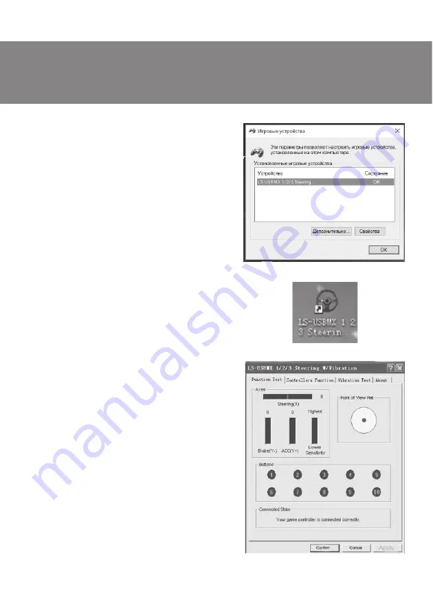
Choose Controllers to set axes and buttons (Fig. 8).

Setting  of  axes  and  buttons  (not  compatible 
with OS Vista 64) 

!

Dead Zone setup: controller will not respond to a 

slight  touch  of  acceleration  pedal  (Accelerate  Y+), 

or  brake  pedal  (Brake  Y-),  or  turns  of  the  wheel 

(Steering  X),  therefore  necessary  adjustments 

should be made by cursors (Fig. 8);

!

Sensitivity  setup:  the  higher  sensitivity  is,  the 

swifter and more e cient response of controller to 

pressing  of  pedals  and  turns  of  the  wheel  will  be, 

therefore  necessary  adjustments  within  Lower  to 

Higher range should be made by cursors (Fig. 8);

!

KeyMap Setup reprograms functional keys: there 

should  be  chosen  new  necessary  assignment 

against the key designation (Fig. 8);

!

After installation of the driver, the controller can 

be  automatically  centered  by  pressing  MODE 

button 

k

.

ATTENTION!  During  automatic  calibration  do 
not press any buttons.

Fig. 6

Fig. 5

Fig. 7

Summary of Contents for GC-W400

Page 1: ...www sven GC W400...

Page 2: ...RUS 1 2 3 4 5 6 7 8 UKR ENG www sven 2 RUS 2 3 3 3 3 3 4 5 7 8 15 SVEN 2017 SVEN PTE LTD 1 0 V 1 0...

Page 3: ...1 GC W400 GC W400 4 2 3 1 1 1 CD 1 1 1 4 2 10 180 Windows XP Vista 7 8 10 USB 8 10 5 USB Windows XP Vista 7 8 10 RUS 3 GC W400...

Page 4: ...RUS m 1 6 a b 5 8 c d 8 e f g 9 h 1 4 i MODE j 10 k MODE l m n USB o p 2 4 3 o p n a f l b c d e f g a b h i f j k l MODE 9 1 7 5 6 8 2 3 10...

Page 5: ...RUS 5 GC W400 7 5 2 3 RJ 11 m USB n USB CD setup exe Controllers Function 8 Vista 64 Dead Zone setup Accelerate Y Brake Y Steering X 8 Sensitivity setup Lower Highest 8 KeyMap Setup 8 6 5 7...

Page 6: ...RUS MODE k Vibration test 9 Vibration strenght 9 85 Left force Both force Right force 9 Con rm Force Feedback Stick Volume Road Effects Collision Engine MODE k Digital Analog f 8 9...

Page 7: ...RUS 7 GC W400 8 Game Controller Con rm USB Force Feedback Force Feedback...

Page 8: ...www sven GC W400...

Page 9: ...SVEN 2017 SVEN PTE LTD i 1 0 V 1 0 RUS UKR 1 2 3 4 5 6 7 8 ENG i www sven 2 8 10 10 10 10 10 11 12 14 15 9 UKR GC W400...

Page 10: ...10 UKR 1 GC W400 GC W400 4 2 3 1 1 1 CD 1 1 1 4 2 10 180 Windows XP Vista 7 8 10 USB 8 10 5 USB Windows XP Vista 7 8 10...

Page 11: ...11 UKR GC W400 6 a b 5 8 c d 8 e f g 9 h 1 4 i MODE j 10 k MODE l m n USB o p m 1 2 4 3 o p n a f l b c d e f g a b h i f j k l MODE 9 1 7 5 6 8 2 3 10...

Page 12: ...12 UKR 7 5 2 3 RJ 11 m USB n USB CD setup exe Controllers Function 8 Vista 64 Dead Zone setup Accelerate Y Brake Y Steering X 8 Sensitivity setup Lower Highest 8 KeyMap Setup 8 6 5 7...

Page 13: ...13 UKR GC W400 MODE k Vibration test 9 Vibration strenght 9 85 Left force Both force Right force 9 Con rm Force Feedback Stick Volume Road Effects Collision Engine MODE k Digital Analog f 8 9...

Page 14: ...14 UKR 8 Game Controller Con rm USB Force Feedback Force Feedback...

Page 15: ...www sven GC W400 OPERATION MANUAL Game Racing Wheel...

Page 16: ...ve arisen from the information contained in the given Manual BUYER RECOMMENDATIONS Unpack the device carefully Make sure there are no accessories left in the box Check up the device for damage if the...

Page 17: ...Protect the device from direct impact of high humidity dust strong magnetic elds vibrations high temperatures toxic liquids and gases Instructions for device maintenance for cleaning the case of the...

Page 18: ...d e f g a b h i f j k l MODE 9 1 7 5 6 8 2 3 10 6 CONSTRUCTION a Racing wheel b Buttons 5 8 c Rubber inserts d D Pad e ON OFF LED indication f Paddle shifters g Button 9 h Buttons 1 4 i ON OFF MODE i...

Page 19: ...ad Zone setup controller will not respond to a slight touch of acceleration pedal Accelerate Y or brake pedal Brake Y or turns of the wheel Steering X therefore necessary adjustments should be made by...

Page 20: ...ustments in the setup window against Stick Volume Road Effects Collision Engine etc Switching modes Game racing wheel is equipped with MODE button k for switching between Digital Analog modes i e swit...

Page 21: ...with other peripherals settings D Restart your PC if the controller still doesn t work normally After exiting the game disconnect the controller from the USB port and connect it again If it still can...

Page 22: ...233 65 89 98 www sven 12 2 176 02 02 427447 48310 15 Manufacturer SVEN PTE LTD 176 Joo Chiat Road 02 02 Singapore 427447 Produced under the control of Oy Sven Scandinavia Ltd 15 Kotolahdentie Kotka F...

Reviews: