background image


Page 5 of 10 


6. 

Operation 

 
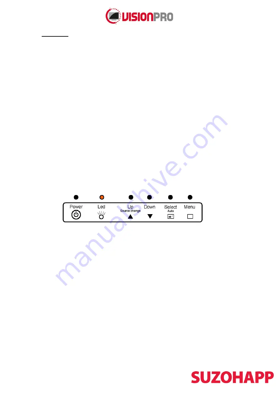
Color LED: 

This LED shows the state of controller.  

Green is the 

“normal state”. 

Red is the “Off mode”. (Can’t find Sync. signals)  
Amber is the 

“DPMS mode” (

Display Power Management Signaling). 


 PC Settings: 

The PC needs to be set to an appropriate graphics mode that has the same resolution 

with the LCD panel to have clear screen image. And the vertical refresh rate should be set to one of 
56~75Hz, non-interlaced signal. 

LCD display System Settings: 

The OSD (On Screen Display) provides certain functions to have 

clear image and others. This board supports 5 buttons OSD operation as a standard. The control 
functions defined on OSD operation are as below. 

Pc Graphics Output: 

Signal quality is very important, if there is noise or instability in the PC graphics 

output this may result in visible noise on the display. Refer to the graphic modes table in specification 
section for supported modes. Non-interlaced & interlaced video input is acceptable. 

(If installed) USB cable:

 Plug the USB cable to the connector on the backside of the monitor.


VGA cable: 

Plug the VGA cable to the connector on the backside of the monitor. 

DVI-D Cable:

 Plug the DVI-D Cable (Not included) to the connector on the backside of the monitor. 

Power supply: 

Plug the 24V power supply (Not included) to the connector on the backside of the 

monitor (separate power supply 182-0520). 

Power on: 

Switch on the monitor by using the on/off switch on the OSD control buttons. 

PC Setting: 

The controller has been designed to take a very wide range of input signals however to


optimize the 

PC’s graphic performance we recommend choosing 60Hz vertical refresh rate this will not 

cause screen flicker. 

OSD Control Board: 

The OSD (On Screen Display) provides certain functions to have clear image 

and others. This board supports 4 buttons OSD operation as a standard. The control functions defined 
on OSD operation are as below. 


The chosen OSD settings will be stored in memory. The OSD menu can be cleared from the screen 
from the screen by moving the selection bar to the EXIT MENU icon pressing the SEL button 
otherwise it will be automatically cleared after a few second ofnon-use. 

Summary of Contents for Vision Pro 150TFT 2302 Series

Page 1: ...nitor Model 150TFT X 2302 XX Manual Version 1 2 Jan 2015 Antonie van Leeuwenhoekstraat 9 3261 LT Oud Beijerland The Netherlands Phone 31 0 186 643333 Fax 31 0 186 643322 Email info suzohapp nl Web eu...

Page 2: ...troduction 3 2 Safety 3 3 Model descriptions 3 4 Monitor connection 3 5 Monitor specifications 4 6 Operation 5 7 OSD MENU 6 8 Driver software touch screen optional 150TFTS2302MG 8 9 Mounting instructi...

Page 3: ...mpressed air To clean the monitor use a cloth lightly damped with a mild detergent If the liquid crystal materials leaks from the panel it should be kept away from the eyes or mouth In case of contact...

Page 4: ...Frequency Hz 55 60 75 DVI D Input DATA CLK VPP 450 500 900 Display Characteristics Item Unit Specifications Screen Diagonal inch 23 Active Area mm 509 184 H x 286 416 V Pixels 1920x1080 RoHS Complianc...

Page 5: ...USB cable Plug the USB cable to the connector on the backside of the monitor VGA cable Plug the VGA cable to the connector on the backside of the monitor DVI D Cable Plug the DVI D Cable Not included...

Page 6: ...chosen OSD settings will be stored in memory The OSD menu can be cleared from the screen by pressing the MENU button otherwise it will be automatically cleared after a few seconds of non use OSD Main...

Page 7: ...00 Phase 30 0 100 Color Color Status Management User User Warm Normal Cool Red 50 0 100 PC ONLY Green 50 0 100 Blue 50 0 100 Auto Color To Start OSD Language English English Deutsh Francais Italiano E...

Page 8: ...r information for other operating systems are available on the 3M Touch Systems web site at http solutions 3m com wps portal 3M en_US TouchSystems TouchScreen Your monitor is Plug and Play compliant I...

Page 9: ...ow the steps described below Place the monitor into the machine Place the M4 screws on the both sides of the monitor Tighten the nuts until the monitor is firmly secured to the machine do not use scre...

Page 10: ...049 Power supply input 100 240V output 12V 5A 22 0012 4 Power cable Euro lead 1 80M 149 0112 11 VGA cable 1 80m 149 0147 USB cable type a b m m 1 80M 149 0121 DVI D Cable 2 mtr 18 1 149 0111 2 Serial...

Reviews: