Introduction
Technical Handbook
019722-101 Rev. 05
8
SC-350/360
>>>
3.4 Positional References
Unless stated the contrary, positions and directions such as left, right,
upper, lower, clockwise and counterclockwise are given with respect
to the machine when viewed from the front.
3.5 Modes of Operation
Refer to the
User’s guides
for information.
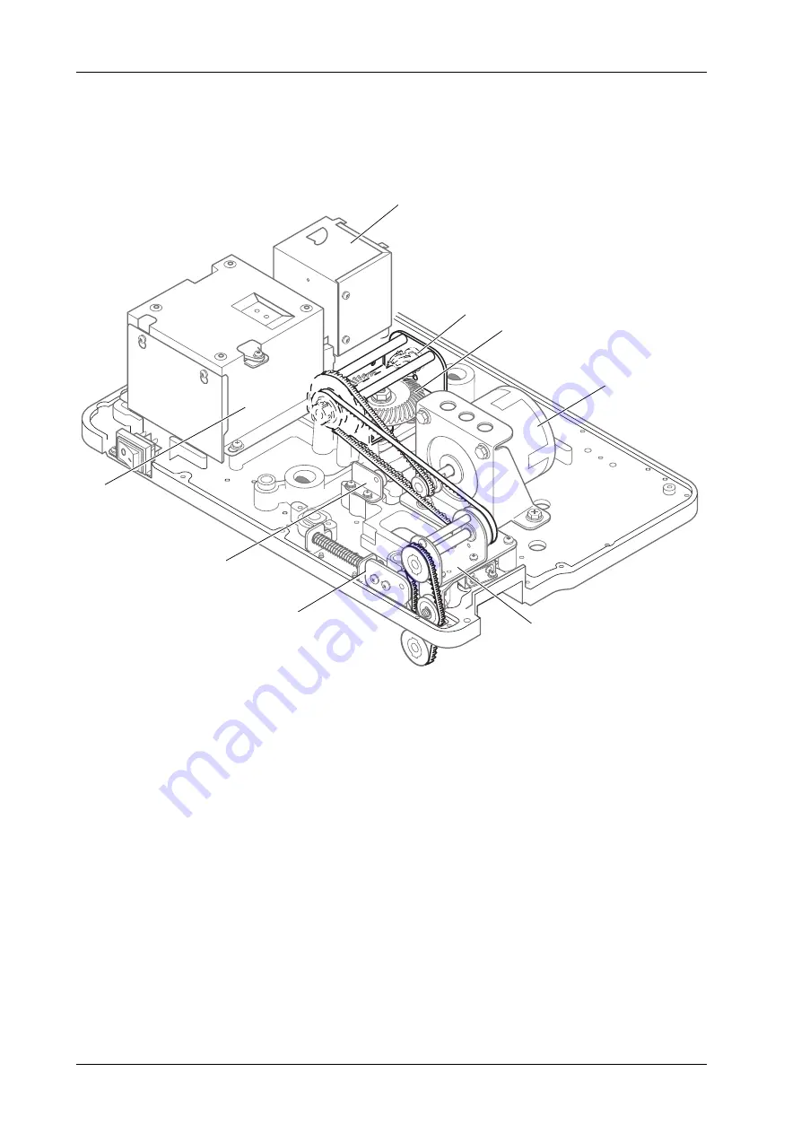
Machine turned upside down
9 Serial Interface & RD/AUX box
10 Pulley stand - Coin disc drive
11 Gear - Coin disc drive
Shaft and Bearing
12 Main motor
13 Pulley stand - Feeding
14 Belt stretcher
15 Support roller
16 Power supply box
9
10
11
12
13
14
15
16


