background image


104 

6.2. View Setup 

6.2.1. Switching Between Different Screen Divisions 

Creating and Using New Screen Divisions 

When a view is created, it has a default screen division setting, however when using 

the view, it may be useful to change the number of screen divisions. This does not 

create a different view, but divides the existing view into a new set of divisions. 


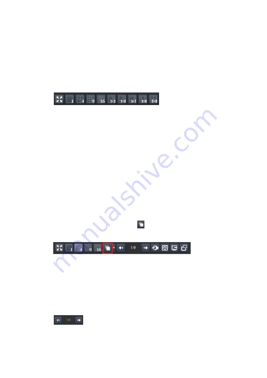
To perform this function within the  view, simply click the button corresponding to 

the view that you want to use. The buttons are located in the area above the main 

view window. 


After  you  have  clicked  on  the  desired  view,  the  cameras  will  be  divided  into 

separate pages  in the  selected view; the  formula is  36/selected view  number. For 

example, a one view will have a 36 pages of views and a 1+5 view will be 36/6, 6 

pages of views.  


Auto-flipping Pages 

When multiple pages of screen divisions exist, you may choose to automatically flip 

between the pages by clicking on the 

 button. Clicking the button again will end 

the automatic flip function. 


Screen Division Page Use 

The page number is displayed to the right of the view buttons. Clicking on the arrow 

button to the right  of the page number or clicking on the current screen partition 

button  will  scroll  through  the  pages  in  order.  Clicking  on  the  arrow  button  to  the 

left of the page number will scroll through the pages in reverse order. 


Summary of Contents for NVR7312(2U)

Page 1: ...NVR7300 Series User Manual Release 1 2...

Page 2: ...vides an overview of Server surveillance functionality and includes the functions of Video Management Software for operating and monitoring a Server network Version History Ver Version Description Dat...

Page 3: ...fitness for any particular purpose Furthermore Surveon Technology reserves the right to revise this publication and to make changes from time to time in the content hereof without obligation to notif...

Page 4: ...tures and Benefits 21 1 2 Specifications for the NVR7300 Series 22 1 2 1 Hardware Specifications 22 1 2 2 VMS Specifications 23 Chapter 2 Hardware Overview 25 2 1 Front Panel 25 NVR7316 25 2 2 Rear Pa...

Page 5: ...ware Introduction 40 3 2 Module Framework 41 3 3 System Architecture 42 3 3 1 Standalone Server Client Server All in One 43 3 3 2 Standalone Server Remote Client Web Client SPhone Client 44 3 3 3 Mult...

Page 6: ...Unit 64 4 5 Connections Expansions 67 4 5 1 System Connections for Initialization 67 4 5 2 SAS Interface 68 4 5 3 Powering Up 69 Connecting the power cord 69 Powering up the equipment 69 4 5 4 Status...

Page 7: ...iew Window Overview 101 6 2 View Setup 104 6 2 1 Switching Between Different Screen Divisions 104 Creating and Using New Screen Divisions 104 Auto flipping Pages 104 Screen Division Page Use 104 Fishe...

Page 8: ...ng Recording 126 7 1 4 Storage Management 128 7 1 5 Pre Post Recording 131 7 1 6 Individual Schedule 132 7 1 7 EonOneLite 134 Chapter 8 Camera Setup 135 8 1 Adding Cameras 135 8 1 1 Automatic Scan for...

Page 9: ...tion 164 Testing Tampering Detection 165 8 4 4 Forbidden Area Detection 166 Enabling or Disabling a Detection 166 Configuring and Editing Detection Windows 166 Testing Detection Windows 167 Deleting a...

Page 10: ...s 178 Testing Detection Windows 178 Deleting a Dividing Line 179 Enabling or Disabling a Detection 179 8 4 10 Go In Out Detection 180 Configuring and Editing Detection Windows 180 Testing Detection Wi...

Page 11: ...97 Conditions 198 Sensor Input 199 Clock Alarm 199 Disk Error 200 Video Loss 200 Actions 200 Event Log 200 PTZ Control 200 Recording Controls 201 E Mail 201 Alarm Sound 202 Video Popup E Map 203 SMS 2...

Page 12: ...Failover Setting 221 Failover History 225 10 3 Failover Status 226 10 3 1 Failover in Live View 226 Failover Status Icon 226 Failover Status Lights 227 Red Status Failover Icon 228 10 3 2 Failover in...

Page 13: ...4 11 4 1 Creating a VI Search 244 Time Selection 244 Camera Selection 245 Setting New Search Criteria 246 11 4 2 Using the Search Results 247 Selecting the Result 247 Result Playback 247 11 5 Event Se...

Page 14: ...a 265 12 1 4 Image 265 12 1 5 PTZ 266 12 1 6 Preset 266 12 1 7 Patrol 266 12 1 8 Edit Camera 266 12 1 9 Mask 267 12 1 10 Optimize 267 12 2 External 268 12 2 1 I O Box 268 Add 268 Edit 270 Delete 270 1...

Page 15: ...nOneLite 283 12 5 Alarm 284 12 5 1 Rule 284 12 5 2 Email Notification 284 12 5 3 SMS Notification 285 12 5 4 Digital I O 285 12 5 5 FTP Setting 286 12 6 Account 287 12 6 1 Accounts 287 Enable LDAP 288...

Page 16: ...04 12 9 4 License 305 12 9 5 Backup System 306 Add a Backup Schedule 306 Edit a Backup Schedule 308 Stop a Backup Schedule 309 Delete a Backup Schedule 310 12 9 6 Clear SCC Data 310 12 9 7 Remote Assi...

Page 17: ...scriptions 325 Playback 326 PTZ Preset 326 DI DO 327 Info 327 13 5 Installing and Starting the SPhone Client on Android Devices 328 13 5 1 Installing the SPhone Client Optional 328 13 5 2 Starting the...

Page 18: ...Configuration to Multiple Cameras 359 Backup Configuration 360 14 6 Event Log 362 Search 362 Export 363 Appendix 364 A Technical Specifications 364 Connection Interface 364 CPU Operating System Hard D...

Page 19: ...ection The device should be installed according to specifications Provide a suitable power source with electrical overload protection Do not overload the AC supply branch circuit that provides power t...

Page 20: ...Access Location like computer room The access can only be gained by SERVICE PERSONS or by USERS who have been instructed about the metal chassis of the equipment is have energy hazards that service p...

Page 21: ...30 days Based on the client server architecture the NVR7300 provides high I O large capacities and overall system stability necessary for scalable projects The NVR7300 also comes with the enterprise V...

Page 22: ...2 0 x 2 USB3 0 x 2 VGA x 1 HDMI x 2 Mic In port x 1 Speaker out port x 1 RAID RAID 1 5 6 1 Spare 5 Spare 6 Spare Electrical Dual Redundant PSU 460W Operating Environment Temperature 5 C to 40 C Humidi...

Page 23: ...ack eMap functions depends on product Direct display to secondary monitor s Investigation Search by date time and camera Search by VI event combinations Search over multiple days Search over multiple...

Page 24: ...sion IQinvision Mobotix Panasonic and more Storage Expansion Built in RAID storage management Recording to iSCSI NAS Backup to iSCSI NAS General Misc Video privacy mask Digital zoom in zoom out Log vi...

Page 25: ...including Service Power Cooling Fan Thermal System LEDs 3 Handle To pull push the enclosure out and into the cabinet when the enclosure is installed on a slide rail rackmount system 4 Power Button Po...

Page 26: ...ons at the rear 2 Power supply unit cooling module The hot swappable PSUs provide power to the system There is a cooling module within each PSU WARNING Do NOT remove the non redundant components Do NO...

Page 27: ...ack or cabinet Internal Backplane An integrated backplane separates the front and rear sections of the chassis This circuit board provides logic level signals and low voltage power paths Thermal senso...

Page 28: ...ly status LED 3 Cooling module status LED 4 Temperature sensor status LED 5 System fault LED 6 Power button 7 Mute service button WARNING If critical faults are indicated on the LED panel verify the c...

Page 29: ...Thermal Green Amber Green indicates that the internal temperature is within the safety threshold Amber indicates that the internal temperature has gone over the safety threshold 5 System fault Green...

Page 30: ...d the drive trays may not fit into the drive bay Drive Tray LED Two LED indicators are located on the right side of each drive tray When notified by a drive failure message you should check the drive...

Page 31: ...31 2 5 Controller 2 5 1 Controller Type There are two types of controller panels The main difference is the LEDs Type II controller will be used for illustration purposes Type I Type II...

Page 32: ...headphone jack 6 Reserved LEDs 15 1 Gb s Ethernet 7 6Gb s SAS expansion port 16 1 Gb s Ethernet Wake On LAN 8 miniUSB COM port 17 1 Gb s Ethernet 9 D Sub VGA port Res 1920 x1080 60Hz Note The managem...

Page 33: ...uring the initialization process 2 Host Busy Green Blinking Green to indicate traffic on the host bus 3 Cache Dirty LED Amber Amber indicates the following Cache Memory is dirty Errors occurred with c...

Page 34: ...n indicates 1Gb connection established Off Off indicates 10 100Mb connection established or no connection established 2 Link activity Amber Steady amber indicates a connection has been established Fla...

Page 35: ...ature sensor fails Elevated temperature if the temperature breaches the upper threshold set for any of the interior temperature sensors During the system initialization stage the cooling fans operate...

Page 36: ...When either of the unit fails you need to replace the PSU as soon as possible PSU Cooling Module Status LED Status Description Flashing Green The system is connected to power supply but the power swit...

Page 37: ...audible alarms Audible Alarms If any of the following components fails the audible alarm will be triggered Cooling fan modules PSU modules Hard disk drives Sensors or presence detection circuitries If...

Page 38: ...ng the rotary switch on the LED panel For example the firmware automatically disconnects the second JBOD if it is connected online and comes with an ID identical to that of the first JBOD NOTE The IDs...

Page 39: ...are being replaced The following components can be user maintained and hot swappable PSU including cooling modules Hard drive NOTE Normalized airflow ensures sufficient cooling of the system and is on...

Page 40: ...nt server mode The Local Client and Local Domain Server run for standalone SMR NVR VMS Server while the Remote Client receives live video streams and event video playbacks from LAN or Internet All adm...

Page 41: ...default configuration point for NVR2000 series which do not have a Local Client Web Client for simple use Remote access an ActiveX application OCX installed on remote PCs for live viewing and event p...

Page 42: ...re i7 980X or above Intel Core i7 860 or above Intel Core i5 650 or above Memory 4 GB or above Display nVidia GeForce GTX660 2GB or above Hard Drive SATA 7200 RPM 500 GB or above Network 1 Gbps or abo...

Page 43: ...erver IP cameras are all in the same LAN Use NVR as Server No installation needed Use PC as Server Install both the VMS NVR Server and VMS Client on a PC Insert the VMS IPCAM product CD Click VMS Suit...

Page 44: ...is needed for live video monitoring event recording playback access Also the Web Client an ActiveX application OCX can be used for basic live viewing and event playbacks through the web browser while...

Page 45: ...e installation Client Install the VMS Client on PCs Insert the NVR SMR product CD Click VMS Client on the menu to start the installation Install the Web Client on the PCs Optional Launch Microsoft Int...

Page 46: ...ameras and the PC are all in the same LAN while the other IP cameras are installed in remote location with Public IP 3 3 3 Multiple Servers SCC Client For users with multiple SMR NVR Servers SCC Clien...

Page 47: ...the VMS NVR Servers on PCs Insert the VMS IPCAM product CD Click VMS Suite on the menu to start the installation Choose Advanced Setup to uncheck the VMS Client The VI Server can also be unchecked if...

Page 48: ...in Server only SCC Client Install the SCC Client on PCs Insert the NVR SMR product CD Click SCC Suite on the menu to start the installation Choose Advanced Setup to select the SCC Client only Note 1 F...

Page 49: ...be opened while using port forwarding to access the VMS Server Stream Port 9090 Doman Data Port 9060 Log Download Message Port 15507 and Log Download Data Port 9080 Access through a firewall Use port...

Page 50: ...network nodes obtain Internet access through a DSL or cable modem connected to a router or network address translator NAT NAPT Hosts on the private network are connected to an Ethernet switch or comm...

Page 51: ...ding for Accessing VMS Server To enable port forwarding for accessing VMS Server please follow the steps below 1 Do Router Port Mapping for VMS NVR Server Go to VMS Setup Network Port Mapping in VMS a...

Page 52: ...se which are unchangeable Global Ports The public ports for remote clients to connect to the internal VMS NVR Server The Global ports are changeable but the simplest way is to make them the same with...

Page 53: ...53 Log Download Data Port TCP 9080 Note Camera port default 80 and stream port default 6002 for accessing cameras should be opened while VMS NVR Server and the cameras and are not in the same LAN...

Page 54: ...elow Storage Hard Drives Note The hard drives should be purchased separately 4 1 2 Checklist for Network Topology Make sure you have the right switch hub for your environment Either of the following o...

Page 55: ...came with the slide rail kit Item Description Quantity 01 Mounting bracket assembly left side 1 02 Mounting bracket assembly right side 1 03 Inner glides 2 04 Flathead screws 6 32 L4 6 05 Truss head s...

Page 56: ...rail 3 Adjust the length by loosening the four screws on the slide rail Secure the slide rails to front and rear posts using truss head screws 05 and tighten the four screws on the slide to fix the l...

Page 57: ...57 6 Make sure the inner glides on both sides of the enclosure meets the inner glide rail Secure the enclosure using M5 or M6 screws from the front U N L O C K U N L O C K U N L O C K...

Page 58: ...hardware asp 4 3 1 Prerequisites Hard drives are separately purchased and when purchasing hard drives the following factors should be considered Capacity MB GB Use hard drives that have the same capac...

Page 59: ...ion is the maximum capacity of the smallest drive Note Hard drives dedicated for OS will have certain storage capacities that are unavailable for use towards the total storage capacity WARNING Make su...

Page 60: ...tems 1 2 3 4 5 6 7 8 9 10 11 12 13 14 15 16 3U systems The general alignment is from left to right and or top to bottom in numeric order as shown below Hard Drive Slot 1 Hard Drive Slot 2 Hard Drive S...

Page 61: ...me 4 3 3 Replacing a Hard Drive Installing 3 5 HDD Removing the HDD tray Press the release button to open the bezel and gently pull the HDD tray out of the enclosure Attaching the HDD The interface co...

Page 62: ...ay bezel open Once the hard drives have been installed in the drive trays the drive trays are ready to be installed into the system With the tray bezel open insert the installed hard drive and tray in...

Page 63: ...rm with support personnel on PCI E card qualification before purchase installation 1 Loosen the screws and remove the covers shown in the illustration below 2 Install the PCI E card into PCI E slot Se...

Page 64: ...ware User Manual in the CD ROM for details 4 4 4 Replacing Power Supply Unit A failed PSU should be replaced as soon as possible but only when you have a replacement module in your hand Contact your v...

Page 65: ...s 3 To remove the PSU module pull the extraction handle downwards to disconnect the PSU from the backplane connectors Once dislodged gently pull the PSU out of the system If the system is mounted in a...

Page 66: ...inting outwards Push the replacement PSU into the chassis and when you feel the contact resistance push the extraction handle towards the PSU module and it should engage the back end connectors 5 Fast...

Page 67: ...t TWO hard drives upon initialization The system connection requires the user to 1 Connect an Ethernet cable from the system to a switch router 2 Place the CD that came with the system into your PC s...

Page 68: ...be separately purchased and applied The single controller JBODs do not require MUX kit Dual ported SAS and Single port SATA Connectors WARNING The hard drives and drive trays should only be installed...

Page 69: ...ering up the equipment 1 Power up the networking devices 2 Power up the JBODs if applied by pressing the power switches on the rear panel 3 Power up the system by switching on both power switches show...

Page 70: ...please contact customer support Front panel LEDs Drive tray Power Status LED On green Verifying the status LEDs rear of enclosure Observe the rear of the enclosure If the LED indicators show differen...

Page 71: ...allocated for each JBOD Configuring enclosure IDs The configurable IDs for JBODs are from 1 to 15 Usually the numbering starts from the one closest to the managing RAID enclosure Make sure a unique ID...

Page 72: ...72 1st JBOD 2nd JBOD Last JBOD...

Page 73: ...on controller contains a circuit board within a metal canister interfaced through hot swap docking connectors at the back end Two SAS wide ports on the interface faceplate connect to a managing RAID s...

Page 74: ...of the 4 PHYs links has failed OFF indicates all 4 PHYs are offline 2 SAS Speed Green Amber Green indicates 6Gbps link speed Amber indicates 3Gbps link speed OFF indicates no connection 3 Ctrl Status...

Page 75: ...connection interfaces U S B 3 0 p o r t s U S B 2 0 p o r ts H D M I 1 H D M I 2 J B O D S A S e x p a n s i o n D S u b V G A p o r t E t h e r n e t p o r ts o p t i o n a l E t h e r n e t p o r t...

Page 76: ...Series system is powered on Username The username of the domain which is always admin Password The password of the domain Default password is admin Auto Login Check this option and you do not have to...

Page 77: ...ard drives 2 Confirm the number of your hard drives the system will auto detect the number of installed hard drives Check if the detection result is correct if yes click Yes and proceed or Next to go...

Page 78: ...on but maximum capacity 2 All of HDDs RAID 1 Best protection Your data will be mirrored 2 Half of HDDs RAID 5 Use 1 disk to store the parity function data to provide fault tolerance 3 HDD number minus...

Page 79: ...y before configuration 3 1 Default recording behavior Select the best recording method When Always recording is selected every image will be recorded When Motion recording is selected only motion dete...

Page 80: ...will be affected Set up the time zone before setting up the time Note Date Time should be set correctly before recording 4 1 Time synchronization There are options to choose from Time synchronization...

Page 81: ...xt to go to the next step Basic settings 5 Basic Settings You can change or use the default password Check the Use Default Password option if you wish to keep the default password If you want to chang...

Page 82: ...ecting input the relevant information and check Enable DHCP service on this NVR to confirm the setting Warning Make sure that only 1 DHCP server is activated in your system otherwise it may cause netw...

Page 83: ...and go to the next step Progressing If you wish to set up the local display you can click this item and go to the Local display page Local display Select the best method for your scenario to have a b...

Page 84: ...sing After clicking Next on the summary page the wizard will start to initialize your system This act will take a few minutes to complete Once it is done the system will reboot automatically 9 All com...

Page 85: ...detect the cameras in the same LAN Click the detection result to go to the next step Add camera Click Finish to close this window You can add cameras later in the setup page 10 Add camera The detecte...

Page 86: ...86 Click Finish to close this window You can also add cameras later in the setup page After the wizard installation is done you will see the Live View page from the Local Client...

Page 87: ...tallation package and unzip the downloaded file In the extracted folder double click setup exe to launch the installation wizard 3 Click the EonOne Lite shortcut on your Desktop to launch the web base...

Page 88: ...ou can see the RAID level and the capacity of the partition which is about to be created from the newly added storage device and its connected JBODs if any Step 2 Creating a partition Click Apply to c...

Page 89: ...n your Server click Setup to bring out VMS Setup window and then select Record to see and click Storage option for Storage Manager 2 All available Logical Drives as well as their sizes free space and...

Page 90: ...gs In General tab click Check 4 Choose the RAID level and then click Create Logical Drive to create the RAID configuration The system supports recording to ISCSI and NAS 5 In IP Storage tab you can au...

Page 91: ...re targets Delete Click Delete to delete the selected Refresh Click Refresh to refresh Target Click Targets to see the setup result 6 In NAS tab you can add NAS in as the video storage Click Add and i...

Page 92: ...92...

Page 93: ...ra information 5 2 1 Automatic Scan for Cameras Right click on the Default Group area to bring out the setting menu and select Scan For Camera 1 The system will respond by beginning an automatic scan...

Page 94: ...SCH Dahua Dynacolor EDIMAX EverFocus HIKVISION IQinvision JVC LG Panasonic Surveon and ONVIF Model 2 To add a camera to the system check the box by the camera entry You may also check the Select All b...

Page 95: ...ea to bring out the setting menu and select Add Camera to manually add a camera to the Server 2 In the camera window fill out the following information IP Address Camera Port This value will automatic...

Page 96: ...value will automatically populate with the default value for the Vendor and Model selected User Name This value is not always required Password This value is not always required Camera Name It is rec...

Page 97: ...ule Click to bring out VMS Setup window and select Record and then Schedule 1 The schedule grid corresponds to every hour in the week Click on one of the 4 recording methods and then click on the grid...

Page 98: ...98 2 Click the Apply button to apply the schedule and OK to exit the dialog...

Page 99: ...the optimum viewing angle to discern a situation The default view setting is 4x4 From the Camera List you can click and drag each camera into separate frames The camera output will be displayed in th...

Page 100: ...100...

Page 101: ...w Window Overview The live view window is split into 10 distinct parts 1 Live View Playback Selection Tabs Allows users to choose live view and playback mode 2 Camera List Lists all the connected came...

Page 102: ...full screen mode go to the next previous page go home and auto page flip between pages Full screen mode Viewing screen modes Auto page flip between pages When there are more than 1 live view page cli...

Page 103: ...ginal image window an enlarged window and the original fisheye view Date and time Signed in User Account Logout About contains version and product information Enclosed with the user manual Setup butto...

Page 104: ...d view the cameras will be divided into separate pages in the selected view the formula is 36 selected view number For example a one view will have a 36 pages of views and a 1 5 view will be 36 6 6 pa...

Page 105: ...is installed to have a best viewing result Ceiling Mount Table Floor Mount or Wall Mount Icon Description Reference conventional rectilinear projection panorama view split window horizontal view 4 spl...

Page 106: ...he colored box in the original fisheye window on the upper right corner to have a detailed view projected original fisheye view Fisheye Tracking Select one camera and click the Fisheye button in the t...

Page 107: ...e E map button in the button area to open an existing E map or create an E map When there is an existing E map the E map will be shown as below You can click the set camera on the map to see its surro...

Page 108: ...s no E map stored the system will ask you to add an E map Follow the steps below to create an E map 1 Prepare layout drawings or a map of the area being surveyed 2 Click the Add button to bring out th...

Page 109: ...to the Camera List tab to drag and drop the cameras to the desired location on the E map to complete the E map creation For camera relocation click to select the cameras and then the selected camera...

Page 110: ...t can be changed within the live view window 6 3 1 Object Tracking Object tracking can be used to track object Only one channel could be added to do the object tracking Select one channel Right click...

Page 111: ...rd will zoom in scrolling backward will zoom out Click the corners of the box and drag to the area of interest The main picture will show the digitally zoomed output while the picture and picture will...

Page 112: ...lowing table explains the buttons Snapshot Audio volume Time range can be set when viewing the playback Full frame mode Key frame mode Saves video clips Exports selected clips Clear all the Cue Ins an...

Page 113: ...the previous segment Jumps to the next segment The play speed can be adjusted from 1x to 8x 6 3 4 Manual Recording When recording schedules are set it may be necessary to manually record a video strea...

Page 114: ...114 6 3 5 Others Image Settings Camera image settings can also be accessed by right clicking the panel containing the camera video and selecting Others Image Settings...

Page 115: ...differences in lighting Hue The color cast of the image This value can be used to compensate for colored lighting or other color casting Sharpness The edge contrast of the image This value can be use...

Page 116: ...in the top right corner to close the image Insert HTML The HTML overlay function allows simple integration of web applications in the VMS by replacing one or more panels of the screen with an active...

Page 117: ...e larger division To perform this action right click the panel corresponding to the camera and choose Others Send to Large Channel Reconnect In some cases it may be necessary to manually reset the con...

Page 118: ...io Resize to Fit Window The image can be set as the length width ratio or resize to fit window by clicking Others Keep Video Length Width Ratio Resize to Fit Window Object Counting can only be set via...

Page 119: ...full screen mode by clicking on the full screen button located above the main viewing window Optionally you may also choose to view a single frame in full screen mode by double clicking on the frame...

Page 120: ...r Settings The following sections deal with Server settings that can be configured under the Server Settings menu 1 Click to bring out VMS Setup window and select System and then select General Server...

Page 121: ...r 30 days Click on the items in the Position section and use the Up and Down buttons to change the storage priorities Time Setup To set the server time click on the number you wish to change and enter...

Page 122: ...nal server to enable this functionality And input the IP address of the external server in the External Server field Check the option Make this NVR as an NTP server to enable this functionality And ch...

Page 123: ...123 7 1 2 To Perform Notification Setting 1 Click to bring out VMS Setup window and select Alarm and then select Email Notification or SMS Notification...

Page 124: ...d These address es will receive notifications from the Server Multiple addresses can be entered by separating individual addresses with semi colons E mail Sender Enter a valid E mail address in the fi...

Page 125: ...numbers Optional If a SIM PIN is required enter the PIN code in the PIN field Note that applying incorrect PIN code may disable your SIM card Note To change the PIN code remove the SIM card from your...

Page 126: ...and select Record and then Schedule The schedule grid corresponds to every hour in the week Click on one of the 2 recording methods and then click on the grid area to paint in the method for the corr...

Page 127: ...127...

Page 128: ...er click to bring out VMS Setup window and then select Record to see and click Storage option for Storage Manager 2 All available Logical Drives as well as their sizes free space and status will appea...

Page 129: ...oose the RAID level and then click Create Logical Drive to create the RAID configuration The system supports recording to ISCSI and NAS 5 In IP Storage tab you can authenticate targets by clicking CHA...

Page 130: ...delete the selected Refresh Click Refresh to refresh Target Click Targets to see the setup result 6 In NAS tab you can add NAS in as the video storage Click Add and input the required information to a...

Page 131: ...several minutes before and after the occurrence of an alarm Click to bring out VMS Setup window and select Record and then select Pre Post Recording The following pop up window will appear In each of...

Page 132: ...132 7 1 6 Individual Schedule Schedules can be set for individual camera Click to bring out VMS Setup window and select Record and then select Individual Schedule...

Page 133: ...hen click on the grid area to paint in the method for the corresponding hour Click OK to save the settings and exit the dialog Click Copy Settings to have the same settings applied to other cameras On...

Page 134: ...neLite Click to bring out VMS Setup window and select Record and then click EonOneLite Click Continue to open EonOneLite platform Click Shutdown to end NVR service Note Only specific NVR models suppor...

Page 135: ...in the Camera List below the Live View 8 1 Adding Cameras Cameras can be added to the Server in two ways via an automatic scan or by manually inputting the camera information 8 1 1 Automatic Scan for...

Page 136: ...Name The default camera name Make Model Vendor Including ACTI Afreey AXIS Arecont BOSCH Dahua Dynacolor EDIMAX EverFocus HIKVISION IQinvision JVC LG Panasonic Surveon and ONVIF Model IP Address Userna...

Page 137: ...Port The web access port default is 80 Vendor Changing this value will affect connectivity Model Changing this value will affect connectivity Stream Port Default is 6002 User Name This value is not al...

Page 138: ...g out the setting menu and select Add Camera 2 In the camera window fill out the following information IP Address Changing this value will affect connectivity Camera Port The web access port default i...

Page 139: ...era Name It is recommended you change this value if you have more than one camera of this make model Camera Icon Select or change icon here 8 1 3 Managing Group To edit to add and to delete a group cl...

Page 140: ...em will ask for a group name Input a group name and click OK Rename the group 1 To rename a group click on the group you d like to rename to bring out the editing window 2 Input a new group name and c...

Page 141: ...141 8 1 4 Search Camera Input the query in the search box and press Enter to search from the added cameras...

Page 142: ...eral settings include network connectivity settings as well as basic camera name description and icon settings 1 Right click the camera entry and select Camera Settings General Camera Or click to brin...

Page 143: ...address for the camera If you wish to automatically assign an IP address to the camera use DHCP services If you wish to assign a fixed IP select Fixed IP Address and provide an IP address for the came...

Page 144: ...will automatically populate with the default value for the Vendor and Model selected Stream Port This value will automatically populate with the default value for the Vendor and Model selected Camera...

Page 145: ...2 2 Edit Camera 1 Right click the camera entry and select Camera Settings Edit Camera for settings to the selected camera Or click to bring out VMS Setup window and select Camera and then select Edit...

Page 146: ...Setting an incorrect username or password may affect camera connectivity and configurability 3 Changing the Camera Model and Vendor In certain situations it may be necessary to change the Vendor or M...

Page 147: ...s can be configured within the server To configure the information for the on screen display 1 Right click on the specific camera and select Camera Settings OSD to bring out the OSD settings menu Or c...

Page 148: ...OSD settings Choose any of the following options Show Name Displays the input text on video Show Date Displays the camera date Show Time Displays the camera time Click Copy Settings to have the same s...

Page 149: ...149 2 Once Copy Settings button is clicked the following window will appear Select the cameras you d like to have the same settings applied to save time...

Page 150: ...s Privacy masks can be added on the video Right click on the specific camera and select Camera Settings Mask to bring out the privacy mask settings menu Or click to bring out VMS Setup window and sele...

Page 151: ...d by a border 2 Click and drag the overlay to move the overlay around the screen Click and drag one of the six dots on the border to resize and reshape the overlay If multiple windows are present the...

Page 152: ...152 4 The masked areas will be shown in black on the live view screen after the mask is saved To delete the setting go back to Mask Settings click Clear to delete the setting...

Page 153: ...3 1 Camera Image Settings To configure camera image settings Right click the specific camera entry and click Image Image Or click to bring out VMS Setup window and select Camera and then select Image...

Page 154: ...Adjust the following sliders to change the camera image Brightness The overall lighting level of the image This value can be used to boost or reduce the apparent lighting of the image Saturation The...

Page 155: ...to compensate for colored lighting or other color casting Sharpness The edge contrast of the image This value can be used to make the picture appear clearer 2 Click OK to save your changes 3 Click Cop...

Page 156: ...ck the specific camera entry in the Camera List below the Live View then click Image Advanced Video Or click to bring out VMS Setup window and select Camera and then select Advanced Camera Select a sp...

Page 157: ...ncoding Method drop down Encoding methods will vary by camera type but common ones include MJPEG H264 2 Select a video resolution from the Resolution drop down Supported resolutions will vary by camer...

Page 158: ...ed Quality The camera bitrate will be adjusted to meet the quality selected in the dropdown Dropdown values will vary by camera 5 Click Copy Settings to have the same settings applied to other cameras...

Page 159: ...159 8 4 VI Setup Right click the specific camera entry in the Camera List below the Live View then click VI Setup Or click to bring out VMS Setup window and select VI...

Page 160: ...gs or else the operation will fail 2 If a new window is desired enter a name in the New Window Name field and click the New button Up to 3 detection windows can be set for each camera The current wind...

Page 161: ...1 Right click the camera entry in the Camera List below the Live View then highlight and click the VI Setup Camera Motion Select Camera 2 Click the Close at the top right corner of the window to dele...

Page 162: ...t a specific camera for VI Setup 2 Check the Enable Event box to enable detection or uncheck the box to disable detection 3 Click OK to save the changes and exit the popup Configuring and Editing Dete...

Page 163: ...is saved image to compare with the live recording image to see if there is any different when the 2 images are different the alarm will be triggered 3 Click the Begin Simulation button enable test det...

Page 164: ...g Select Camera option Select a specific camera for VI Setup 2 Check the Enable Event box to enable detection or uncheck the box to disable detection 3 Click OK to save the changes and exit the popup...

Page 165: ...ve Reference Image to have a reference image saved and the system will use this saved image to compare with the live recording image to see if there is any different when the 2 images are different th...

Page 166: ...Enable Event box to enable detection or uncheck the box to disable detection 3 Click OK to save the changes and exit the popup Configuring and Editing Detection Windows To configure a new detection w...

Page 167: ...VI Setup Forbidden Area Select Camera option 2 Click Save Reference Image to have a reference image saved and the system will use this saved image to compare with the live recording image to see if th...

Page 168: ...cific camera for VI Setup 2 Check the Enable Event box to enable detection or uncheck the box to disable detection 3 Click OK to save the changes and exit the popup Configuring and Editing Detection W...

Page 169: ...ct is missing before an event is triggered 8 Click OK to save the changes and exit the popup Testing Detection Windows To test a detection window 1 Right click the camera entry in the Camera List belo...

Page 170: ...ht click the camera entry in the Camera List below the Live View then highlight and click the VI Setup Intrusion Select Camera option 2 Highlight an existing detection window 3 Click the Clear button...

Page 171: ...cific camera for VI Setup 2 Check the Enable Event box to enable detection or uncheck the box to disable detection 3 Click OK to save the changes and exit the popup Configuring and Editing Detection W...

Page 172: ...efine the minimum size of the fence crossing objects that will be detected 6 Adjust the sliders Settings will be applied to all existing windows Duration Sec Adjusts how much time between each check f...

Page 173: ...Click End Simulation to end the simulation 5 Click OK to exit the popup Deleting a Detection Window To delete a new detection window 1 Right click the camera entry in the Camera List below the Live Vi...

Page 174: ...a specific camera for VI Setup 2 Check the Enable Event box to enable detection or uncheck the box to disable detection 3 Click OK to save the changes and exit the popup Configuring and Editing Detec...

Page 175: ...entry in the Camera List below the Live View then highlight and click the VI Setup Missing Object Select Camera option 2 Click Save Reference Image to have a reference image saved and the system will...

Page 176: ...t box to enable detection or uncheck the box to disable detection 3 Click OK to save the changes and exit the popup Configuring and Editing Detection Windows To configure a new detection window 1 Righ...

Page 177: ...w then highlight and click the VI Setup Foreign Object Select Camera option 2 Click Save Reference Image to have a reference image saved and the system will use this saved image to compare with the li...

Page 178: ...ion button to create a new dividing line Only 1 dividing line can be set for each camera 3 Click and drag the created dividing line to the desire position and direction 4 If an object size has not yet...

Page 179: ...ne 3 Click the Clear button to delete the line 4 Click OK to save the changes and exit the popup Enabling or Disabling a Detection To enable or disable the detection functions 1 Right click the camera...

Page 180: ...n Zone and click the New Region button to create a new window Only 1 detection window can be set for each camera 3 Click and drag the white dots along window border of a window to resize or reshape th...

Page 181: ...w detection window 1 Right click the camera entry in the Device Browser then highlight and click the VI Setup Go In Out Detection option 2 Highlight an existing detection window 3 Click the Clear butt...

Page 182: ...5 1 PTZ Settings The PTZ settings deal with the software PTZ control panel These settings adjust how much the camera will pan tilt zoom and focus with each control panel input Note You must be logged...

Page 183: ...bring out VMS Setup window and select Camera and then select PTZ Select a specific camera for advanced camera settings Note You must be logged into the camera before changing settings or else the oper...

Page 184: ...be grayed out Auto Pan Speed The speed which the camera will pan between the mechanical stops when the Auto Pan function is activated Pan Speed The distance the camera will pan to each side Tilt Speed...

Page 185: ...rder to move the camera quickly to a point of interest To configure camera PTZ preset settings right click the specific camera with the PTZ functionality then highlight and click PTZ Setup Preset opti...

Page 186: ...You must be logged into the camera before changing settings or else the operation will fail The popup will display the camera output as well as a Position Setting pad Note You must be logged into the...

Page 187: ...desired type a name into the Preset Point Name field 3 Click the Add a preset point to add the preset to the list Click OK exit the menu or you may continue to add delete additional presets Deleting a...

Page 188: ...cally using the patrol functionality This function basically moves the camera between preset points in a fixed pattern To configure camera patrol settings Right click the specific camera with the PTZ...

Page 189: ...Select a specific camera for advanced camera settings Note You must be logged into the camera before changing settings or else the operation will fail 1 On the right side of the popup there will be a...

Page 190: ...h preset point before continuing from the Dwelling Time Sec dropdown 3 Select one of the following Stop Time The camera will stop the number of minutes specified in the box between patrol sessions Con...

Page 191: ...rform PTZ related functionalities Note 1 The camera to be controlled must be selected by highlighting it clicking its output window in the main view window 8 5 5 Directional Pad Pan and Tilt The pan a...

Page 192: ...r stop pan between the mechanical stops Patrol In cameras with PTZ functionality one camera can be used to survey a large area This can be done automatically using the patrol functionality Zoom The zo...

Page 193: ...193 8 6 Deleting a Camera Right click the camera entry you wish to remove to bring out the options popup Highlight and click the Delete Camera option...

Page 194: ...t will correspond to the settings on the Server To perform this operation 1 Right click the camera entry you wish to remove to bring out the options popup Highlight and click the Optimize option Or cl...

Page 195: ...195 Select a specific camera for advanced camera settings Note You must be logged into the camera before changing settings or else the operation will fail...

Page 196: ...as the setup of alarm rules and schedules 9 1 Alarm Rules VMS Client provides robust alarm handling features To access these features click to bring out VMS Setup window and select Alarm and then Rule...

Page 197: ...actions that can be undertaken when an alarm is triggered 4 Schedule Allows the user to schedule the application of specific alarm rules This is useful in cases such as applying rules to non office ho...

Page 198: ...ion Foreign Object Detection Forbidden Area Detection Intrusion Detection Go In Out Detection Missing Object Detection Tampering Detection Camera Motion Detection Virtual Fence Tailgating Detection Af...

Page 199: ...il button will pull up the Sensor Input Settings menu listing all the cameras From this menu click the checkboxes next to the cameras that will be used to trigger the Alarm Optionally check the All Ca...

Page 200: ...sed to trigger the Alarm Optionally check the All Cameras check box to use all the cameras available Click the OK button to exit the menu Actions The following alarm actions can be taken when the alar...

Page 201: ...uration slider Click Apply to save the settings 5 Click OK to exit the menu Recording Controls When the alarm is triggered the system records video onto the storage Clicking on the Action button will...

Page 202: ...ss will be the default sender listed in E mails sent from the Server Need Account Check Tick this option to check Username Enter the user name for the Server email account in the Username field Passwo...

Page 203: ...he alarm is triggered a popup video appears on the local client Clicking the Action button will pull up a menu SMS When the alarm is triggered an SMS message will be sent Checking this option will bri...

Page 204: ...essage delivery 3 Optional If a SIM PIN is required enter the PIN code in the PIN field Note that applying incorrect PIN code may disable your SIM card Note To change the PIN code remove the SIM card...

Page 205: ...put duration from 0 to 60 seconds 4 Click the OK button to exit the menu FTP Setting When the alarm is triggered the file will sent to FTP server such as snapshot files Complete FTP setting and click...

Page 206: ...isable button to bring up a paintbrush 3 Click the cursor on the table to paint in a schedule You may click and drag to paint a wide area For example if you wish to disable the alarm on Tuesday at 6pm...

Page 207: ...all the events that occur on the system You can find the event log on the left corner of the live view page Click on the Details button to see the View Log window Or click to bring out VMS Setup windo...

Page 208: ...208 The view log splits into three types System concerning with individual modules Event concerning with cameras and Operation concerning with users...

Page 209: ...e Query Log dialog box Within this dialog users may choose to narrow the search to the three major event types by selecting the checkbox beside the event type System These are errors that occur within...

Page 210: ...arch can be done over all cameras by choosing All User Name Using the User Name subfield a search can be narrowed down to an individual user This selection list contains all the users configured on th...

Page 211: ...alarms NOTE The VI detection should be set beforehand and the Video Popup E Map should be enabled to activate this functionality Go to VMS Setup Alarm Rule Action Video Popup E map to activate this f...

Page 212: ...nge can be set when viewing the playback Full frame mode Key frame mode Saves video clips Exports selected clips Clear all the Cue Ins and Cue Outs Set Cue In marker for clip start Set Cue In marker f...

Page 213: ...video playback Pause video playback Stops video playback Jumps to the previous frame Jumps to the next frame Jumps to the previous segment Jumps to the next segment The play speed can be adjusted fro...

Page 214: ...of the Live View page Red light indicates something is not right while the green light shows everything is ok System Status Hover over the System Status Icon to see the CPU and Memory usage Network S...

Page 215: ...215 Camera Status Hover over the Camera Status Icon to see the camera status and see which one is out of order Recording Status The overall recording status is shows as green or red...

Page 216: ...the user to manage workgroups adding managing multiple NVR devices scanning NVR devices and configure Failover control storage manager etc VMS Client provides Workgroup features To access these featur...

Page 217: ...local NVR as the backup server with default setting When the Protected NVR is failed to connect for 1 minute then the system will recognize this device as failed NVR The backup server will automatical...

Page 218: ...kgroup and then Multiple NVR After entering Multiple NVR management it appears an empty table for first time users Users could firstly add NVRs by automatically scanning or by adding IP addresses one...

Page 219: ...ease wait for a while This step may take longer time to process the full list Check the device names to add to the list and click OK Use default ID password to access and click OK After successfully a...

Page 220: ...220 Refresh Click Refresh button It will renew the order of the items in the list Delete Select one device Click Delete button to remove the device from the workgroup...

Page 221: ...lover Setting After adding all NVR devices in Multiple NVR go to FailOver Setting The NVR devices have been added to the Failover list To enable failover function check the item Enable FailOver and se...

Page 222: ...management Sync Now In the Setting tab selecting one Protected NVR click Sync Now button The system will start to synchronize the device When completed the pop up window will show success message The...

Page 223: ...223 Also after selecting one detail item users could check and change settings and advanced settings using the following buttons Information Edit Delete or Setting...

Page 224: ...selection appears if checked the Share column will show Yes to represent public shared Delete Delete the device from the list Setting Setup other advanced setting of the device Set the log and locati...

Page 225: ...ge Entering IP address and other information editing NAS or deleting NAS here Failover History In the Setting tab click History button The History table shows failover records of protected servers inc...

Page 226: ...following table the system fast starts failover protection status Go to VMS WorkGroup FailOver Setting The small failover icon will appear on the top right corner of Live View When disables failover f...

Page 227: ...ackup status and red green lights There are 3 backup statuses Active Inactive or Standby For protected server the red light indicates connection failure and the green light indicates normal connection...

Page 228: ...the icon representing each device will list in the section When the protected server terminates connection for 1 minute the failover will take over tasks of failed NVR The icon of this device will tu...

Page 229: ...229 10 3 2 Failover in Playback Playback Status In Playback status play the selected video Select one protected server and drag it to the view screen...

Page 230: ...cking the play button The blue bar represents recording of failover server when the protected server interrupts and the failover takes over The green bar represents normal recording of the protected s...

Page 231: ...11 1 Introduction Note You must be logged into a server to access playback functionality Click on the Playback tab in the live view screen The VMS has 3 distinct playback functions Time Search Plays b...

Page 232: ...232 11 2 Time Search 11 2 1 Creating a Time Search Specified Time Use the arrows calendar and time boxes to specify a specific period for search playback...

Page 233: ...of these options can be chosen by clicking on corresponding button in the button area above the main view screen In both cases functionality and operation is the same 11 2 3 Camera Selection Once a t...

Page 234: ...the timeline The amount of time displayed in the timeline can also be adjusted using the slider located next to the scrollbar Sliding the indicator toward the right will cause a smaller amount of time...

Page 235: ...must start playback separately for each feed you wish to view The following table explains the buttons Sync all the views to play videos from the same period of time While in the Sync mode the view c...

Page 236: ...frame Jumps to the next frame Jumps to the previous segment Jumps to the next segment The play speed can be adjusted from 1x to 8x Capturing Screenshot 1 Click the Snapshot button located in the butt...

Page 237: ...ed is reached click the Cue In button 3 When the end of the segment to be captured is reached click the Cue Out button 4 A popup window will appear for confirmation 5 Click Yes when confirmed Click No...

Page 238: ...238 11 3 Backup Search 11 3 1 Creating a Backup Search Specified Time Use the arrows calendar and time boxes to specify a specific period for search playback...

Page 239: ...an be chosen by clicking on corresponding button in the button area above the main view screen In both cases functionality and operation is the same 11 3 3 Camera Selection Once a time period has been...

Page 240: ...the timeline The amount of time displayed in the timeline can also be adjusted using the slider located next to the scrollbar Sliding the indicator toward the right will cause a smaller amount of time...

Page 241: ...playback to jump to the point that you have clicked on You must start playback separately for each feed you wish to view The following table explains the buttons Snapshot Audio volume Time range can...

Page 242: ...the Snapshot button located in the button area 2 The snapshot will be stored in the USB device Please have your USB device ready Capturing Video Clip 1 Make sure that the video clip is playing 2 When...

Page 243: ...243 5 Click Yes when confirmed Click No and redefine the Cue In and Cue Out 6 The video will be stored in the USB device Please have your USB device ready...

Page 244: ...e VI search click the VI icon next to the fisheye icon in the button area 11 4 1 Creating a VI Search Time Selection Use the arrows calendar and time boxes to specify a specific period for search play...

Page 245: ...ameras available for each period will be listed in the Camera List These cameras can then be dragged into one the search playback box es Select a camera to perform the VI search on by clicking its ent...

Page 246: ...within the search range that trigger the VI set up Search Step Finds the first event that triggers the VI then stops The next event can be found by repeating the same search 5 Click Search to begin t...

Page 247: ...the event occurred Event Type The type of VI detection that the event triggered Label A user defined label optional Updated The last time the event was updated Result Playback Once a result is selecte...

Page 248: ...rts selected clips Clear all the Cue Ins and Cue Outs Set Cue In marker for clip start Set Cue In marker for clip end Automatic reply the clip From Cue in to Cue Out Play backwards Starts video playba...

Page 249: ...249 Jumps to the next segment The play speed can be adjusted from 1x to 8x...

Page 250: ...11 5 Event Search An Event search involves searching for multiple tagged events over one more cameras To access the Event search click the Event Search icon next to the VI Search icon in the button a...

Page 251: ...back Once a date is selected clicking on the boxes will allow you to specify a specific period to search playback in 10 minute increments Camera Selection Once a time period has been selected the came...

Page 252: ...y This will display an initial thumbnail of the camera output Setting Event Search Criteria 1 Selecting Ignore will search for all labels Choose an Event Type and or a Label to search for 2 Click Sear...

Page 253: ...l optional Updated The last time the event was updated Result Playback Once a result is selected by clicking on it playback can be started by double clicking on the thumbnail Alternatively you may rig...

Page 254: ...he following functions are available for playback Snapshot Audio volume Time range can be set when viewing the playback Full frame mode Key frame mode Saves video clips Exports selected clips Clear al...

Page 255: ...ip From Cue in to Cue Out Play backwards Starts video playback Pause video playback Stops video playback Jumps to the previous frame Jumps to the next frame Jumps to the previous segment Jumps to the...

Page 256: ...256 11 6 Fisheye Search 11 6 1 Creating a Fisheye Search Specified Time Use the arrows calendar and time boxes to specify a specific period for search playback...

Page 257: ...n Once a time period has been selected the cameras available for each period will be listed in the Camera List These cameras can then be dragged into one the search playback box es Select a fisheye ca...

Page 258: ...Floor Mount or Wall Mount Icon Description Reference conventional rectilinear projection panorama view split window horizontal view 4 split windows 3 enlarged view windows and 1 original fisheye windo...

Page 259: ...59 windows 1 enlarged view window and 1 an original fisheye window Place the colored box in the original fisheye window on the upper right corner to have a detailed view projected original fisheye vie...

Page 260: ...the timeline The amount of time displayed in the timeline can also be adjusted using the slider located next to the scrollbar Sliding the indicator toward the right will cause a smaller amount of time...

Page 261: ...he timeline will cause playback to jump to the point that you have clicked on You must start playback separately for each feed you wish to view The following table explains the buttons Snapshot Audio...

Page 262: ...umps to the previous segment Jumps to the next segment The play speed can be adjusted from 1x to 8x Capturing Screenshot 1 Click the Snapshot button located in the button area 2 The snapshot will be s...

Page 263: ...utton 3 When the end of the segment to be captured is reached click the Cue Out button 4 A popup window will appear for confirmation 5 Click Yes when confirmed Click No and redefine the Cue In and Cue...

Page 264: ...S Setup window and select Camera to set the camera related settings 12 1 1 Advanced Camera Advanced Camera allows you to configure the encoding method resolution maximum frame filter and the quality S...

Page 265: ...Chapter 8 2 3 OSD Settings for more details 12 1 3 General Camera General Camera allows you to configure the camera connection See Chapter 8 2 1 General Camera Settings for more details 12 1 4 Image...

Page 266: ...sets See Chapter 8 5 2 PTZ Preset Settings for more details 12 1 7 Patrol Patrol allows you to configure the PTZ patrol See Chapter 8 5 3 PTZ Patrol Settings for more details 12 1 8 Edit Camera The Ed...

Page 267: ...to configure the privacy mask settings See Chapter 8 2 4 Privacy Mask Settings for more details 12 1 10 Optimize Optimize allows you to configure the camera to the default settings See Chapter 8 7 Opt...

Page 268: ...window and select External to set the external devices related settings 12 2 1 I O Box You can add I O Box to have other external devices connected to the NVR to respond when there triggered Add Clic...

Page 269: ...O Box Port Vendor select from the drop down list Model select from the drop down list Device Name create a name for this device User Name input the username Password input the password 2 Click OK to a...

Page 270: ...or the selected I O Box IP address I O Box Port Vendor select from the drop down list Model select from the drop down list Device Name create a name for this device User Name input the username Passwo...

Page 271: ...ol Connect the joystick controller to the USB port The Joystick Settings Window will prompt after clicking Joystick In this window functions of each button are listed Button Number Function 1 Resets a...

Page 272: ...o pan 7 Manually records the video streams 8 Pops up an instant playback for five minutes 9 Brings up the full screen view 10 Captures a snapshot 11 Increase the zoom distance 12 Decrease the zoom dis...

Page 273: ...required UPS IP Address and click Connect Once the UPS device is connected successfully the manufacture the model the serial number and the estimated protection time will be shown UPS settings Click e...

Page 274: ...re to set the following settings before the connection Go to APC s Administration SNMPv1 access check the option Enable SNMPv1 access and click Apply Go to APC s Administration SNMPv1 access control r...

Page 275: ...275 After the setting you can see the one you have set as below Now you can follow the UPS connection procedures as described above and connect the set APC UPS device to the NVR...

Page 276: ...select VI to set the VI related settings 12 3 1 Camera Motion Detection Camera motion detection involves using the camera hardware to analyze the video feed and detect motion in specified areas See Ch...

Page 277: ...When it moves an alarm will be triggered See Chapter 8 4 2 Object Motion Detection for more details 12 3 3 Tampering Detection Tampering detection involves using the software to determine when the ca...

Page 278: ...etection for more details 12 3 5 Intrusion Detection Intrusion detection involves using the software to analyze the video feed and detect intrusion larger than a certain size See Chapter 8 4 5 Intrusi...

Page 279: ...ect missing objects larger than a certain size See Chapter 8 4 7 Missing Object Detection for more details 12 3 8 Foreign Object Foreign object detection involves using the software to analyze a video...

Page 280: ...8 4 9 Tailgating Detection for more details 12 3 10 Go In Out Go In Out detection involves using the software to analyze the video feed and detect a go in out object crossing over the restricted area...

Page 281: ...to bring out VMS Setup window and select Record to set the recording related settings 12 4 1 Schedule A Recording Schedule can be created to apply to an entire Server See Chapter 7 1 3 Scheduling Reco...

Page 282: ...12 4 3 Pre Post Recording The Server can trace back and preserve video images from several minutes before and after the occurrence of an alarm See Chapter 7 1 5 Pre Post Recording for more details 12...

Page 283: ...283 12 4 5 EonOneLite Enter EonOneLite platform to operate the system See Chapter 4 8 7 1 8 EonOneLite...

Page 284: ...Alarm Rules you can combine the alarm trigger conditions with action items such as event notification video recording and or camera movements See Chapter 9 1 Alarm Rules for more details 12 5 2 Email...

Page 285: ...285 12 5 3 SMS Notification Configure the SMS setting See Chapter 9 1 1 Adding an Alarm Rule for more details 12 5 4 Digital I O It allows you to configure digital I O port settings...

Page 286: ...286 12 5 5 FTP Setting It allows you to configure FTP server settings...

Page 287: ...In this session accounts and their authorities can be edited added and deleted 12 6 1 Accounts The Account List provides the following information about each account Account Name User Group Type for...

Page 288: ...288 Enable LDAP When enable LDAP function apply one server IP and domain name to login to the system Use this domain account to login directly Add Account To add an account to the domain...

Page 289: ...n rights o User This group has no configuration rights and limited VMS Server performance statistics o Viewer This group is limited only to viewing and has no access to configuration or performance st...

Page 290: ...g screen change any of the following account information User Group Selects a user type for this user There are four options o Administrator This group has complete management privileges including acc...

Page 291: ...alid password 5 If desired check the Disable User box to disable this account 6 Click OK to save the changes to the account If the account description user group or status changes it will be reflected...

Page 292: ...reen 4 When prompted to confirm deletion click Yes to delete the account The deletion will be reflected in the Account List Note The Admin account cannot be deleted 12 6 2 Account Authority Settings T...

Page 293: ...293 12 7 Network Click to bring out VMS Setup window and select Network to set the network related settings...

Page 294: ...R Server Login Port 7735 TV Wall Port 2 5 0 7734 1024 9010 Domain Broadcast Port 9030 Domain Client Message Port 9040 Domain Console Message Port 9050 Domain Local Communication Port 9020 Domain Remot...

Page 295: ...the setting of the stream port and the IP address by editing the Server 12 7 3 Multi LAN Multiple network cards can be supported Their information is listed as below Click the Edit to set the Network...

Page 296: ...duties and assign addresses within the range specified Note You may skip this step if you have separate DHCP service Most routing devices will have DHCP capabilities 1 Fill in the following informati...

Page 297: ...using DDNS requires registration on third party websites for DDNS services Select desired DDNS service website check the Enable DDNS option and fill in valid user name and password You can then acces...

Page 298: ...Server The Global ports are changeable but the simplest way is to make them the same with the host ports Please open the listed ports on your router Port Host Global Port Protocol Port Number Domain M...

Page 299: ...12 8 System Click to bring out VMS Setup window and select System to set the system related settings 12 8 1 Log Viewer Log can be viewed under the View Log menu See Chapter 9 2 Event Log for more deta...

Page 300: ...n be configured here View Layout enables the users to select Live View mode After selecting under View Layout section the selected icons will appear on the top of the screen The default setting is 1x1...

Page 301: ...5 Map Editor E map can be configured here See Chapter 6 2 1 5 E map for more details 12 8 6 General Server settings can be configured under the General Server Settings menu See Chapter 7 1 1 General...

Page 302: ...k to bring out VMS Setup window and select Maintenance to set the maintenance related settings 12 9 1 Stream Info From here you can see all the stream information such as channel camera name codec res...

Page 303: ...pgrade patch file in the USB will be read and the upgrading can begin Put the update file to the root directory of the USB device Once the upgrade is done the system will reboot to update the settings...

Page 304: ...import from the file explorer and click Open to import the file 4 Click OK to confirm import The Server will require a restart before imported configurations and files are applied Exporting Parameters...

Page 305: ...vide the extracted file to your distributors or dealers to acquire the license information And they will return the license file License Key Channel Number lis for you to add the channels 4 After rece...

Page 306: ...video recordings can be backed up to USB HDD devices and ISCSI But it is not allowed to use the ones for recording to back up Add a Backup Schedule Go to the Maintenance Backup System Click Add to br...

Page 307: ...t a Task Mode once once a day once a week or once a month Select a start time and an end time Select a backup driver Click OK to confirm the setting When the system is running the backup tasks you ll...

Page 308: ...ce System Backup Select the Task you d like to modify and click Edit to bring out the Edit task window Note Only tasks in the waiting status can be edited For completed or operating tasks users can on...

Page 309: ...irm the change Stop a Backup Schedule Go to the Maintenance System Backup Select the Task you d like to stop and click Stop Note Only tasks in the waiting or running status can be edited For completed...

Page 310: ...10 Delete a Backup Schedule Go to the Maintenance System Backup Select the Task you d like to delete and click Remove 12 9 6 Clear SCC Data It allows you to clear the SCC VMS data on the Domain Server...

Page 311: ...over your system to determine if there is any problem 12 9 8 Database Rebuild This functionality can be used for the technician to rebuild system database after when stop recoding videos and turn off...

Page 312: ...s for viewing 1 Remote Client install Remote Client on remote PCs for live view and playback 2 Web Client use the browser IE Internet Explorer and input the IP address of the camera for live view and...

Page 313: ...ries users have to install VMS Client on remote PC s when distant live viewing and playback are needed 1 Insert the VMS IPCAM CD ROM The CD should auto run If it does not open the CD manually and doub...

Page 314: ...lick Next when you are satisfied with your selection You may choose to install among the following while Advanced Setup Type is selected VMS Server Suite Includes the VMS Server and Local Domain Serve...

Page 315: ...nfirmation screen will display Click Install A progress bar will display indicating installation progress 4 When installation is finished an informational screen will display Click Finish to complete...

Page 316: ...l prompt for a restart A restart is required before the VMS will function correctly You may choose to immediately automatically restart your computer or restart your computer later Clicking Finish wil...

Page 317: ...button to obtain it For users of port forwarding it should be the IP address of the router Port The Login Port for port forwarding 9050 It should be set under Server Other Tasks Port Mapping after the...

Page 318: ...system by pressing the Logout button on the upper right hand corner in the GUI Logging out of individual servers can be achieved by double clicking the server entry and clicking the Yes button on the...

Page 319: ...ord for the domain Default password is admin Language Options for the interface languages Click Login after the username and password are entered After logging in the live view page will be displayed...

Page 320: ...0 13 3 3 PTZ Control Cameras equipped with Pan Tilt Zoom functionality can be controlled directly within the Web Client These controls can be found in the PTZ Control window within the live view scree...

Page 321: ...x2 for playback the viewing stream comes from stream 1 video However if users choose to do 3x3 or 4x4 view screen the viewing stream will come from stream 2 instead The stream of cue in out video will...

Page 322: ...first After the SPhone Client installation is done a login window will pop up Address The IP address for the VMS SMR Server Port The login port for SPhone Client Default port number is 80 Note The por...

Page 323: ...sion Users can see the software version at the lower right corner of the window after logging in 13 4 4 Functionalities on the SPhone Client Live View After logging in you will see the Live View image...

Page 324: ...324 You can click on any channel you d like to see or manage to have a single view on your device...

Page 325: ...or manage Use the playback icon to view the recorded video from the current camera Use the PTZ icon to perform a Pan tilt zoom functionality After tapping the PTZ icon you ll also see a Preset icon U...

Page 326: ...te time to search for the specified videos and use the Previous Next Play Pause icons to view the recorded videos PTZ Preset After tapping the PTZ icon you ll also see a Preset icon Use the Preset ico...

Page 327: ...heck the detailed information of each camera as follows NVR Server The VMS SMR Server name IP Address The IP address for the VMS SMR Server Resolution The video resolution of the camera Quality The vi...

Page 328: ...first After the SPhone Client installation is done a login window will pop up Server Name The VMS SMR Server Name Address The IP address for the VMS SMR Server Port The login port for SPhone Client D...

Page 329: ...329 13 5 3 Checking the Software Version Users can see the software version Tap on the About Us on the upper right corner of the window after logging in...

Page 330: ...13 5 4 Functionalities on the SPhone Client Live View After logging in you will see the Live View images The default is 6 channels per page At most 6 channel live view can be displayed in the same pa...

Page 331: ...331 You can click on any channel you d like to see or manage to have a single view on your device...

Page 332: ...age Use the playback icon to view the recorded video from the current camera Use the PTZ icon to perform a Pan tilt zoom functionality After tapping the PTZ icon you ll also see a Preset icon Use the...

Page 333: ...te time to search for the specified videos and use the Previous Next Play Pause icons to view the recorded videos PTZ Preset After tapping the PTZ icon you ll also see a Preset icon Use the Preset ico...

Page 334: ...heck the detailed information of each camera as follows NVR Server The VMS SMR Server name IP Address The IP address for the VMS SMR Server Resolution The video resolution of the camera Quality The vi...

Page 335: ...ther devices to save time and efforts For easy maintenance the 3 level classified real time event logs critical errors errors and warnings help users to take action efficiently and thus mitigate risks...

Page 336: ...336 2 Accept the terms in the license agreement and click Next...

Page 337: ...337 3 Accept and click Next 4 See if there s any information you d like to change if not click Next...

Page 338: ...ct the setup type typical or custom and click Next If you are not sure which one to select it is recommended to select Typical 6 See if you d like to change the destination folder click Change if not...

Page 339: ...339 7 Click Install to start the installation 8 When the installation wizard completed click Finish...

Page 340: ...340 9 Then the SurveOne Installation Wizard will start Click Next 10 Input the port which is not occupied and click Next...

Page 341: ...341 11 Select the setup type Typical or Advanced and then click Next If you are not sure which one to select it is recommended to select Typical 12 Start to install the SurveOne...

Page 342: ...uter to activate the changes Click Finish to exit 15 After the installation is done and your computer is restarted On your desktop you ll find an IE browser icon with SurveOne on it Double click this...

Page 343: ...343 14 2 Login Log in to SurveOne 1 Go to http 127 0 0 1 XX XX is the port you have setup in the installation wizard 2 Input the default username and password admin and admin 3 Click LOGIN...

Page 344: ...The overall status of NVRs cameras and storage is displayed graphically allowing users to grasp how the systems are at a glance 14 3 1 NVR Status NVR status is classified into 3 groupings Healthy War...

Page 345: ...m will take you to the NVR List to see the detailed NVR status with information such as NVR name model IP address channels and status Click on the to see the details of the NVR including name model IP...

Page 346: ...n the to remove the NVR Click and fill out the pop up form to add NVR 14 3 3 Camera Status Camera status is classified into 3 groupings Connected Events and Disconnected Click on the view all to see t...

Page 347: ...e the detailed Camera status with information such as camera name model IP address and status Cameras under different NVR will be listed separately 14 3 5 Events Status NVR and camera event logs are p...

Page 348: ...With classified event logs users can identify which event needs to take actions first and which not to respond to the situations more quickly and efficiently Use the drop down list to filter the spec...

Page 349: ...r to jump to the corresponding page to see the log 14 3 7 Client List See the client information such as the client IP address and the client version here 14 3 8 Account List See the account informati...

Page 350: ...can easily monitor the system status locally or remotely and ensure the consistent stability 14 4 1 NVR Device See the connected NVR information including CPU memory and disk throughput graphically Cl...

Page 351: ...351 Network See the network status graphically Storage See the storage status including disk volume space information graphically...

Page 352: ...d camera information including camera name model IP address resolution frame rate bit rate and status here Click on the to see more details such as camera name model IP address resolution frame rate b...

Page 353: ...ce SurveOne allows users to do one time setup Users can simply copy the NVR or camera configurations and apply them to new devices to ease the complicated setup process The configurations can also be...

Page 354: ...server DDNS here Click Enable to activate the functionalities You can also click Advanced Setting to fill in further information Enable the Web Server and click Advanced setting to fill in the follow...

Page 355: ...ocal Log Message Download Port 15503 Domain Remote Log Message Download Port 15501 Domain Remote Log Upload port 15505 Domain Local Log Upload Port 40000 NVR Broadcast Port 50000 NVR Message Port DDNS...

Page 356: ...ns can be saved as backup and restored when needed to save time and effort 1 Select Backup or Restore 2 Select path to save the configurations 3 Select which device you d like to save its configuratio...

Page 357: ...the right Multiple IP addresses are supported You can select the Obtain IP Address Automatically or Assign the following IP Address and input detailed information for each NVR Click Back to Workflow...

Page 358: ...358 Click Run to execute the setups now...

Page 359: ...to Multiple Cameras Follow the instruction flow on the right The configurations can be saved as backup and restored when needed to save time and effort Note The source camera and the target camera sh...

Page 360: ...NVR Click Back to Workflow Selection to go back to the previous setting page Click Reset to reset settings on this page Click Run to execute the setups now Backup Configuration Follow the instruction...

Page 361: ...th to save the configurations 3 Select which device you d like to save its configurations Click Back to Workflow Selection to go back to the previous setting page Click Reset to reset settings on this...

Page 362: ...With classified event logs users can identify which event needs to take actions first and which not to respond to the situations more quickly and efficiently Search Use the drop down list to filter t...

Page 363: ...363 Export Click Export the log you re looking for will be copied to the notebook as shown below Click on the number on the upper right corner to jump to the corresponding page to see the log...

Page 364: ...OD models SAS Interface Eight SMP PHYs interfaced through two 12Gb SAS ports Drive Interface channel Supports up to 12 16 channels of 3 6Gbps SAS SATA II SATA III Near line series CPU Operating System...

Page 365: ...Power Factor Correction Yes Hold up Time At least 12ms at 115 230VAC full load after a loss of AC input Over temperature Protection Auto shutdown when lost cooling or exceeded ambient temperature ove...

Page 366: ...d Sea level to 40 000ft Shock Half sine Operating 5G half sine 11ms pulse width Non operating 15G half sine 11ms pulse width Vibration Random Operating 5 to 500Hz 0 25Grms X Y Z 30min Non operating 5...

Page 367: ...013 EMC CE EN 55022 2010 EN61000 3 2 2006 A1 2009 A2 2009 EN61000 3 3 2013 EN 55024 2010 FCC FCC Part 15 subpart B Environment IEC 60068 2 MIL STD 810E 883E ISTA ASTM D3332 IPC TM 650 Others ISO7779 3...

Reviews: