background image

www.surveon.com 


28 

Surveon SMR2006/2010 

3.10. Setting up Live View 

An  important  part  of  monitoring  your  surveillance  network  is  to  have  the  right 

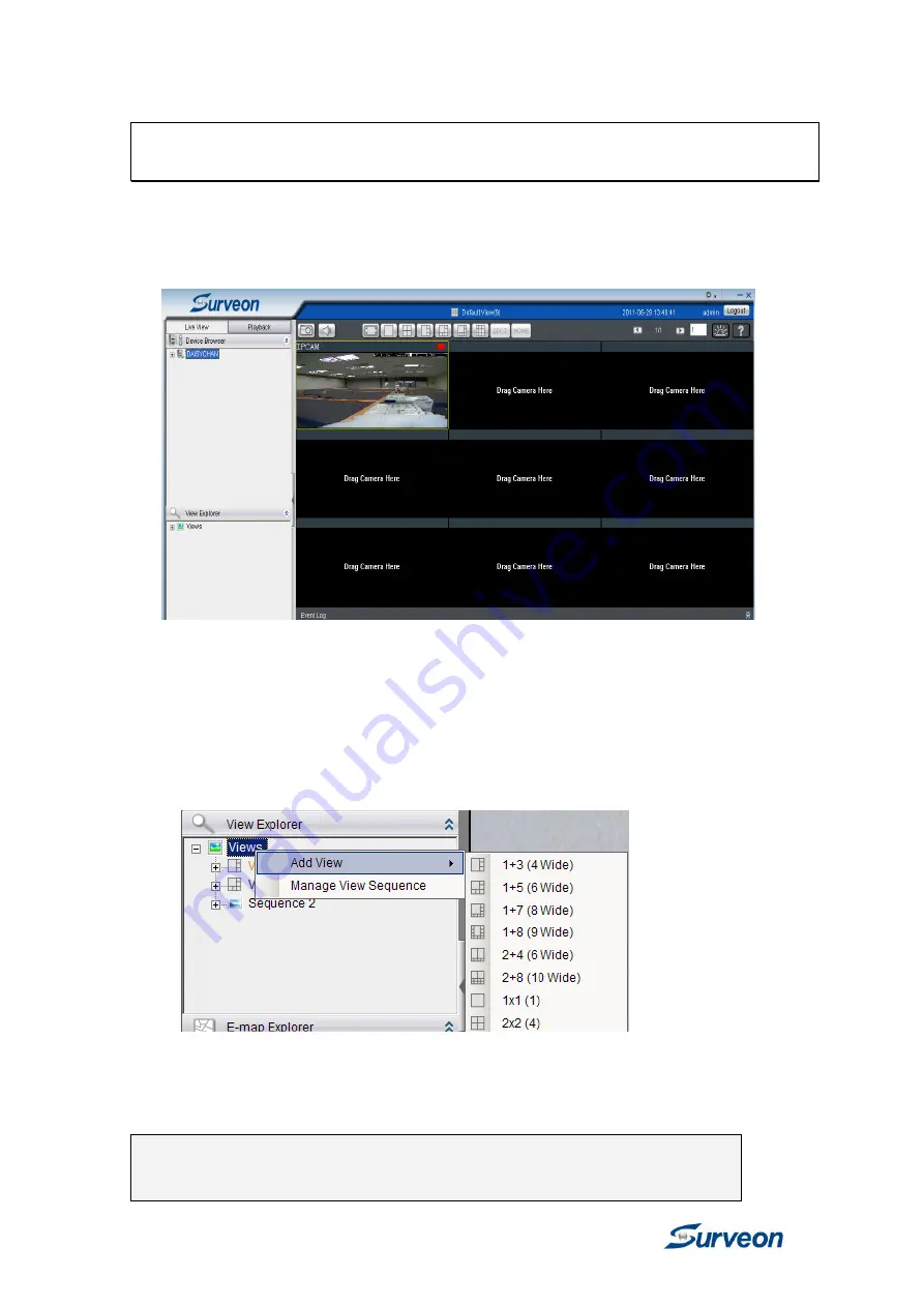
views so that you will have the optimum viewing angle to discern a situation. 

The default view setting is 3x3. 


You can also add a customized view to the VMS Client: 

1.


Right click on 

Views> Add View 

in the 

View Explorer

 window of the 

VMS,  and  choose  the  type  of  view  that  you  wish  to  add.  The 

software responds by placing a blank template in the main viewing 

area. 

2

.  From  the 

Device  Browser 

window,  you  can  click  and  drag  each 

camera into separate frames. The camera output will be displayed in 

the frame.  

Note: 

Dragging a camera into a frame that already has an  assigned camera 

will cause the frame to be reassigned to the new camera.  

Summary of Contents for EMR2000

Page 1: ...SMR2006 2010 Smart Megapixel Video Recorder Hardware Manual Release 1 0 August 2011...

Page 2: ...y or fitness for any particular purpose Furthermore Surveon Technology reserves the right to revise this publication and to make changes from time to time in the content hereof without obligation to n...

Page 3: ...12 2 1 Overview 12 Front View 12 Rear View 12 2 2 Panel Introduction 13 Front Panel Top 13 Front Panel LED 13 Front Panel Bottom 14 Rear Panel Components 14 Chapter 3 Installation Guide 15 3 1 Before...

Page 4: ...agement 22 3 7 Configuring an IP Address for NVR Server 24 3 8 Adding Network Cameras to the Server 25 Auto Scanning for Camera 25 Manually Adding Cameras 26 3 9 Initializing the Camera 27 3 10 Settin...

Page 5: ...alled according to specifications Provide a suitable power source with electrical overload protection Do not overload the AC supply branch circuit that provides power to the device ESD Precautions Ple...

Page 6: ...o radio or television reception which can be determined by turning the equipment off and on you are encouraged to try to correct the interference by one or more of the following measures Reorient or r...

Page 7: ...on is applying its own internal efforts and expertise and is working closely with customers and suppliers to achieve compliance while maintaining an uninterrupted supply of quality products Surveon is...

Page 8: ...8 Revision History Version Description Date 1 0 Initial release August 2011...

Page 9: ...he SMR Series Hardware Specifications SMR2006 2010 System Processor Intel ATOM525 Dual Core 1 8 GHz System Memory DDR3 2GB Chipset Intel ICH9R Disk on Module 4GB Storage 3 5 SATA HDDs x2 HDD hot swapp...

Page 10: ...ayback by video thumbnail 1 8 1 4 1 2 1x 2x 4x 8x play pause stop AVI formated video clip export Instant Playback Supported in video alarm event alarm view functions Pre defined playback durations Vid...

Page 11: ...11 Surveon Smart Megapixel Video Recorder Hardware Manual Language supported English French German Portuguese Spanish Simple Chinese Traditional Chinese...

Page 12: ...iew BACKUP LED Indicators Video Back Up Button Power Switch Hard Drives Inside the Cabinet Front USB Connector Rear View 1 2 USB Port x 4 LAN Port x 2 VGA Port E SATA Port 12V DC In Cooling Fan Restor...

Page 13: ...and network is connected Off Indicates that network is disconnected Network Green Blink Indicates that network activity is in progress On Indicates that the hard drive can be accessed Off Indicates t...

Page 14: ...Panel Components 1 2 E SATA Port USB Port LAN Port Restore Button VGA Port 12V DC In Name Function E SATA x1 Used for connecting the SMR with E SATA drives USB Port x 4 Used for exporting video clips...

Page 15: ...on CAM5210 Network Existing LAN Switch Router or Hub please see the Network Topology below Storage Hard Drives Note The hard drives should be purchased separately Check Network Topology Make sure you...

Page 16: ...uses SATA interface 3 5 inch hard drives Please ensure that you purchase the correct hard drives Placing Hard Drive into Drive Tray Place the hard drive into the drive tray making sure that the interf...

Page 17: ...drive tray with the tray slot into which you wish to insert it Make sure that it is properly aligned and then gently slide it in Note While replacing hard drives users can only extract one drive tray...

Page 18: ...s to the rear panel ports as follows 1 2 USB Port LAN Port VGA Port Insert mouse keyboard or other external devices to the USB port to operate the Video Management Software VMS Insert the LAN cable to...

Page 19: ...witch LED Indicators 1 Press the Power Switch 2 See if the System LED is blinking which means the system is starting up 3 See if the Network LED has turned green which indicates power is on and networ...

Page 20: ...lue the following warning message will prompt out To change the resolution setting please follow the steps below 1 Press Ctrl Shift Esc to call the task manager 2 Go to File New Task Run and then type...

Page 21: ...rt Megapixel Video Recorder Hardware Manual 5 Choose Single Display as the operating mode and Monitor as the display selection in Display Devices Change the screen resolution in Display Settings Click...

Page 22: ...default account to login to the VMS Username admin Password admin 2 Go to Server Setting Storage Manager under the Server entry All available Logical Drives as well as their sizes free space and stat...

Page 23: ...models optimized for I O performance Model Number of Hard Drives Detected 2TB Total Size Default RAID Configuration 2 4TB RAID0 2 2TB RAID1 SMR2006 2010 1 2TB No RAID 5 RAID initialization will begin...

Page 24: ...routing devices have DHCP capabilities 2 If you don t set the fixed IP in the VMS Console first a warning massage will prompt out 1 Login to the VMS Console right click the NVR Manager and click edit...

Page 25: ...e same subnet as the VMS server Auto Scanning for Camera 1 Right click the VMS Server entry and select Scan for Cameras The cameras that can be added to the Server will be displayed To add a camera to...

Page 26: ...hen click OK to add the camera IP Address Camera Port This value will automatically populate with the default value for the Vendor and Model selected Vendor Model Stream Port This value will automatic...

Page 27: ...mart Megapixel Video Recorder Hardware Manual 3 9 Initializing the Camera Right click the camera under the NVR Server and then click Initialize Click Yes These are settings before and after camera ini...

Page 28: ...view to the VMS Client 1 Right click on Views Add View in the View Explorer window of the VMS and choose the type of view that you wish to add The software responds by placing a blank template in the...

Reviews: