Surveillix DVSe16-240-X Hardware Manual Download Page 25


25 


KEYBOARD SETUP 

To attach the keyboard to the recorder, plug the end of the Keyboard into a USB port located on the back of the machine.  


MOUSE SETUP 

To attach the mouse to the recorder, plug the end of the mouse into a USB port located on the back of the machine.  
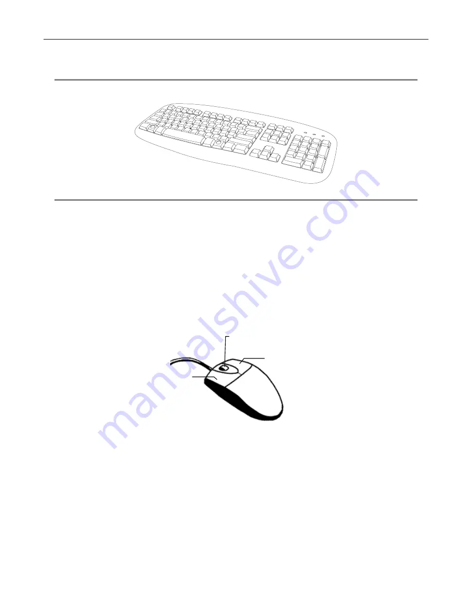
The mouse uses a cursor called a pointer. Pointers come in many different shapes but are most commonly shaped like an arrow. 
The mouse has two buttons: a left button and a right button. Quickly pressing and releasing one of these buttons is called clicking. Sometimes 

you will need to double-click – or click the same button twice quickly. 
In this manual: 
Click means to position the mouse cursor over an item and to single click the left button. 
Right click means to position the mouse cursor over an item and to single click the right button.  
Double-click means to position the mouse cursor over an item and to click the left button twice. 
Select means to position the mouse cursor over a radio button, checkbox, or list item and click on it. 
The scroll wheel in between the two buttons is used for added navigation functionality. By moving the wheel with index finger (scrolling), quickly 

move through multiple pages, lines, or windows. The wheel may also function as a third button allowing the user to quickly click or double-click 

an icon or a selected item 


Right Button 

Scroll Button / Third Button 

Left Button 

Summary of Contents for DVSe16-240-X

Page 1: ...XVSe DVSe Hardware Manual model no Please carefully read these instructions before using this product Save this manual for future use XVSe16 240 X XVSe16 240V X DVSe8 240 X DVSe16 240 X DVSe16 480 X D...

Page 2: ...2...

Page 3: ...S PROFITS BUSINESS INTERRUPTION OR LOSS OF BUSINESS INFORMATION EVEN IF TOSHIBA HAS BEEN ADVISED OF THE POSSIBILITY OF SUCH DAMAGES AND WHETHER IN AN ACTION OR CONTRACT OR TORT INCLUDING NEGLIGENCE Th...

Page 4: ...ur Responsibilities The above warranty is subject to the following conditions 1 You must retain the bill of sale or provide other proof of purchase 2 You must schedule service within thirty days after...

Page 5: ...ce receptacles and the point where they exit from the product 8 Overloading Do not overload wall outlets extension cords or integral convenience receptacles as this can result in a risk of fire or ele...

Page 6: ...iginal part Unauthorized substitutions may result in fire electric shock or other hazards 19 Safety Check Upon completion of any service or repairs to this unit ask the service technician to perform s...

Page 7: ...ght directly from a cool location to a warm location When this product is moved to a hot and humid location from a cool location When this product is moved to a cool and humid location from a warm loc...

Page 8: ...TAGES ARE PRESENT INSIDE THE ENCLOSURE DO NOT OPEN THE CABINET REFER SERVICING TO QUALIFIED PERSONNEL ONLY CAUTION CAUTION TO REDUCE THE RISK OF ELECTRIC SHOCK DO NOT REMOVE COVER OR BACK NO USER SERV...

Page 9: ...in a residential installation This equipment generates uses and can radiate radio frequency energy and if not installed and used in accordance with the instructions may cause harmful interference to r...

Page 10: ...t 5 Repairs or modifications made by the user or caused to be made by the user and carried out by an unauthorized third party 6 Notwithstanding the foregoing Toshiba s liabilities shall not in any cir...

Page 11: ...RODUCT DESCRIPTION 14 FEATURES 15 FRONT PANEL CONTROLS 17 XVSE 17 DVSE 17 REAR PANEL CONNECTORS 18 XVSE 18 16 Channel 240 18 16 Channel 240V 18 DVSE 19 8 16 Channel 19 32 Channel 19 CARD CONFIGURATION...

Page 12: ...G A VIDEO SOURCE 30 8 Channel 30 16 Channel 30 32 Channel 30 CONNECTING SENSORS 31 CONNECTING CONTROL OUTPUTS 31 LOOPING OUTPUTS 32 LOOPING OUTPUT TERMINATION 32 CONNECTING A PTZ CAMERA 33 Attaching t...

Page 13: ...s DVR All troubleshooting and repair procedures that may be shown are for reference and minor repair only Because of the complexity of the individual components and subassemblies no one should attempt...

Page 14: ...ordingly your security investment has never been easier to maintain Multiple users may simultaneously connect through any network connection for instantaneous live viewing digital search and off site...

Page 15: ...T ZOOM Controls Simultaneous Video Search Playback and Backup Video Indexes for Easy Searching Multiple Levels of Security Access Up to 32 Looping Outputs Up to 2 Composite Outputs Up to 32 Network Re...

Page 16: ...16 CONTROLS AND CONNECTIONS This chapter includes the following information Input Output Connector Locations Front Panel Controls and LEDs Rear Panel Connectors...

Page 17: ...val and backup replacement The most common components and buttons are shown below XVSe DVD RW Drive Cooling fan intake Hard drive activity LED Power LED USB ports Power switch DVSe LOCK OPEN LOCK OPEN...

Page 18: ...Video input BNC Sensor inputs Control outputs RCA video out Cooling fan PTZ Optical output USB USB Network eSATA USB Audio input adaptor 5 1 Surround sound Line in line level Speaker out Microphone in...

Page 19: ...1 in CH 2 in CH 3 in CH 4 in CH 5 in CH 6 in CH 7 in CH 8 in CH 9 in CH 10 in CH 11 in CH 12 in CH 13 in CH 14 in CH 15 in CH 16 in 1 2 3 4 5 6 7 8 9 10 11 12 13 14 15 16 CONTROL 1 2 3 4 5 6 7 8 9 10...

Page 20: ...20 Card Configurations 240 PPS 8 16 Channel 240 PPS 32 Channel...

Page 21: ...21 480 PPS 16 Channel 480 PPS 32 Channel...

Page 22: ...22 GETTING STARTED This chapter includes the following information Included Components Setting up the DVR Hardware Optional Components...

Page 23: ...nts to make sure everything has been properly included with the new DVR If any of the following items are missing contact the dealer to arrange a replacement DVR Key Mouse Keyboard Repair Disc Softwar...

Page 24: ...DVRs using the keyboard Hot Swappable Redundant Power Supplies DVSe only Every DVR has the option of a dual redundant hot swappable power supply In the event of a component failure the inoperable powe...

Page 25: ...n twice quickly In this manual Click means to position the mouse cursor over an item and to single click the left button Right click means to position the mouse cursor over an item and to single click...

Page 26: ...ust be capable of having a screen resolution of 1024 x 768 and display colors of at least 32 Bit POWER SETUP WARNING To reduce the risk of electrical shock or damage to the equipment Do not disable th...

Page 27: ...d into the video source DVD Camera etc and plug the other end into the desired BNC input on the recorder Connecting Sensors Each XVSe has 16 Sensor inputs These inputs can be used with devices such as...

Page 28: ...a Form C Relay Looping Outputs The XVSe has 16 Looping outputs Depending on the destination of the outputs each output may have to be terminated The outputs are located on the BNC Connector Cable Atta...

Page 29: ...sing 22 Gauge Twisted Pair It is important to understand how the PTZ connects to the recorder The recorder outputs an RS 232 signal and converts in to an RS 485 signal which is then sent to the PTZ ca...

Page 30: ...ut CH 14 Out CH 15 Out CH 16 Out 16 Channel CH 1 in CH 2 in CH 3 in CH 4 in CH 5 in CH 6 in CH 7 in CH 8 in CH 9 in CH 10 in CH 11 in CH 12 in CH 13 in CH 14 in CH 15 in CH 16 in CH 1 Out CH 2 Out CH...

Page 31: ...an external power supply must be used if power is necessary Connecting Control Outputs Each recorder has up to 16 Control Outputs These outputs can be used to trigger devices such as Sirens Phone Dial...

Page 32: ...tors Make sure there is a video source connected to the input and then connect a cable to the Channel Out on the BNC Connector Cable The looping outs can be connected to video monitors or combined wit...

Page 33: ...the 4 Pin Adapter 1 Locate the PTZ adapter cable 2 Connect the wires of the PTZ adapter to the PTZ camera The yellow wire should connect to the RX on the camera and the orange wire should connect to t...

Page 34: ...rive being removed 8 Turn the Button Lock to the open position and push the Handle Release Button 9 Pull the Release Handle outward while removing the hard drive Reverse steps to install LOCK OPEN LOC...

Page 35: ...ormal circumstances you should not be asked to respond to these messages If you are asked to respond to the messages adding a Printer Monitor etc for the first time follow the instructions carefully A...

Reviews: