


12
ondary coil are fixed in the central core. The two
cores between the coils that are named mobile
nucleus, make up the magnetic flux by moving
the cores and the magnetic-rival to change the
welding output current regularly.
The primary coil is equipped with a temperature
relay that can cut the current when the normal
coil is hotter or above the standard tempera-
ture.
The output cables of the regulator have a con-
venient connection and direct connection.
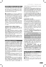
TECHNICAL DATA
SOL5225
INPUT VOLTAGE
(110 - 220) V~
FREQUENCY
60 Hz
PHASES
1 ~
MAX INPUT CURRENT AT 110 V
91 A
MAX INPUT CURRENT AT 220 V
46 A
POWER
11 kVA
NO LOAD VOLTAGE
46 V
WORK VOLTAGE
28 V
WORK CURRENT
210 A
OUTPUT CURRENT RANGE
100-210 A
WORK CYCLE
10 %
WEIGHT
23 kg (50,7 lb)
Place where you will work with the welder:
· Temperature Range: While welding: -10 ~ +
40° C
· During transport or storage: -25 ~ + 55 ° C
· Relative Humidity: At 40 ° C: <50%. / At 20° C:
<90%.
REQUIREMENTS FOR THE MAIN SUPPLY
The voltage oscillogram should show the real
sine wave. The voltage oscillation should not
exceed ± 10% of the nominal value.
CONNECTING THE WELDER
One end of the torch lead is connected to the
welder through the quick connect, and the
other end is connected to the work piece. The
quick joint at the outlet end must be screwed
firmly in a clockwise direction for safety. The
work piece must land on the ground.
NOTE
1. Disconnect the welder from the power source
before connecting the cables.
2. The cables must be connected to the copper
terminal. Use the insulating tape after fixing it
with the bolt and nut.
OPERATION INSTRUCTIONS
ATTENTION: Operating the welder properly
ensures satisfactory operation and prolongs the
service life of the welding equipment. When us-
ing the welder, make sure there is a good input,
output and ground connection before connect-
ing it to electricity.
PROCEDURE FOR THE OPERATION:
1. Turn the power switch on.
2. Adjust the welding current.
3. Operate the welder.
4. Finish the operation.
5. Turn off the ignition switch of the welder.
WELDING
Connect the power input cable and the welding
output cable as indicated in this manual. Then
connect the plug to the electricity before turn-
ing on the switch.
ATTENTION: When there is distance be-
tween the welder and the work piece, the weld-
ing wire must be larger to prevent the voltage
drop from being greater than 4 V.
CLEANING THE PARTS BEFORE THE WELDING
Before carrying out the welding work, be sure
to completely clean the stains of dirt or rust.
However, if the rust is not very important and
the piece does not require much welding, then
it will not be necessary to clean the rust.
ELECTRODE REPLACEMENT
It is only necessary to change the electrodes
when they are consumed and they are at a dis-
tance of 1 ~ 2 cm from the electrode holder.
NOTE: The electrodes are burned at high tem-
peratures. When replacing them, wear gloves.
The rest of the replaced electrode should be
placed in a metal container. Do not use the elec-
trode holder to hold the electrode liner.
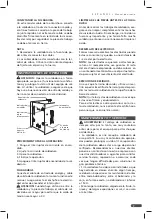
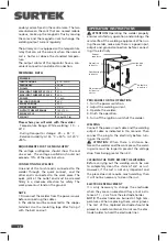
Ignition
switch
Current
regulator.
Operation
indicator
Workpiece
connector.
Electrode
holder con-
nector.
Overheating
indicator.
Summary of Contents for SOL5225
Page 14: ...14 Notas Notes...
Page 15: ...15 Manual de usuario User s manual Notas Notes...