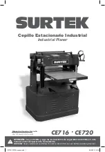
background image

General safety rules

Electric safety

Personal safety

Tool use and care

Specific safety rules for 
industrial planers

Features

Unpacking

Assembly

Adjustments

Operation instructions

Maintenance

Troubleshooting

Technical data

Notes

Warranty policy

Normas generales de seguridad

Seguridad eléctrica

Seguridad personal

Utilización  y cuidados de las 
herramientas eléctricas

Advertencias de seguridad para 
cepillos estacionario industriales

Características

Desembalaje

Ensamble

Ajustes

Instrucciones de operación

Mantenimiento

Solucionador de problemas

Especificaciones técnicas

Notas

Garantía

20

20

20

21

21

22

23

23

25

31

32

32

33

34

36

3

3

3

4

5

6

7

8

9

16

17

18

19

34

36

PELIGRO, ADVERTENCIA, PRECAUCIÓN: 
Indica un riesgo personal o la posibilidad 
de un daño.

DANGER, CAUTION, WARNING: Indicates risk of 
personal injury and/or the possibility  of damage.

2

E N G L I S H


E S P A Ñ O L

CONTENIDO

CONTENT

SÍMBOLOS

SYMBOLS

CE716-CE720 manual.indd   2

29/06/15   16:30

Summary of Contents for CE716

Page 1: ...nt a User s Manual and Warranty ATENCI N Lea entienda y siga las instrucciones de seguridad contenidas en este manual antes de operar esta herramienta WARNING Read understand and follow the safety rul...

Page 2: ...encias de seguridad para cepillos estacionario industriales Caracter sticas Desembalaje Ensamble Ajustes Instrucciones de operaci n Mantenimiento Solucionador de problemas Especificaciones t cnicas No...

Page 3: ...ondiciones de humedad El agua que entre en la herramienta aumentar el riesgo de choque el ctrico No abuse del cable No usar nunca el cable para llevar levantar o desenchufar la herramienta el ctrica M...

Page 4: ...r una persona responsable de su segu ridad Los ni os deben supervisarse para ase gurar que ellos no empleen los aparatos como juguete UTILIZACI N Y CUIDADOS DE LAS HERRAMIENTAS EL CTRICAS No fuerce la...

Page 5: ...ici n de apagado OFF antes de desconectar el cepillo 9 NO MANIPULE el enchufe o cepillo con las manos mojadas 10 USE s lo accesorios tal como se describe en este manual UTILICE s lo accesorios recomen...

Page 6: ...ermanente Los lentes de uso diario no son gafas de seguridad Siempre uti lice gafas de seguridad que cumplen con la norma ANSI Z87 1 cuando opere herramientas el ctricas Algunos ejemplos de estos prod...

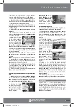
Page 7: ...gurese de encerar antes de ensamblar Compare los elementos con las figuras que se muestran verifique que todos los elementos se encuentren en el empaque antes de tirar la caja ADVERTENCIA Si falta alg...

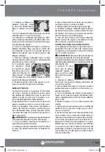
Page 8: ...utilizarse como puntos de elevaci n utilizando un montacargas o gr a de techo Intentar levantar esta unidad sin el equipo adecuado o asistencia adecuada podr a resul tar en una lesi n seria MANUBRIO E...

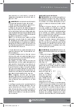
Page 9: ...erre M6 para ensamblar la abrazadera del interruptor en la parte izquierda del cabezal de corte 2 Utilice la llave hexagonal de 5mm y apriete los 2 tornillos hexagonales soc M6 x 16 mm Fig 6 ENSAMBLE...

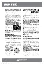
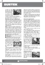
Page 10: ...y 3 pero empiece desde el lado derecho del cuerpo del cabezal de corte y deslice el bloque a la izquierda 5 Refiri ndose de nuevo a sus mediciones con el calibrador de hojillas si la diferencia de un...

Page 11: ...r a 016 reem place la tapa de acceso y vuelva a consultar la secci n de la TABLA DE AJUSTE DEL PARALE LISMO DE LA MESA en la secci n de AJUSTES de este manual INSPECCI N DE LAS CUCHILLAS PRECAUCI N La...

Page 12: ...ra en la figura 16 Las patas del calibrador deben posar de ma nera segura sobre el cabezal Aseg rese de que la varilla del calibrador este paralela al cabezal de corte 5 Baje el tornillo nivelador tan...

Page 13: ...una de las cuchillas est en su punto m s bajo 4 Afloje ambas tuercas de seguro Fig 13g 5 Coloque el bloque indicador bajo el centro de la barra de presi n y ajuste ambos tornillos de fijaci n h hasta...

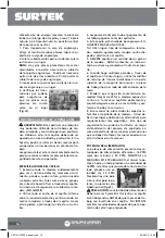
Page 14: ...de la parte superior del cabezal de la pieza fundida 5 Atornille el tornillo de ajuste de baja presi n B hasta que est cerca de 1 4 por encima del cabezal de la pieza fundida La raz n por la que este...

Page 15: ...cluso lesiones serias en el operador u otras personas en el rea de tra bajo NO intente utilizar el cepillo si los dedos de contragolpe no funcionan correctamente POLEAS ADVERTENCIA Cerci rese de que l...

Page 16: ...eg rese de limpiar todo el pegamento de las tablas pegadas antes de cepillarlas 4 Esta cepillo est dise ada para procesar SO LAMENTE MADERA NATURAL NO USE ning n tipo de compuestos lamina dos madera a...

Page 17: ...etamente ADVERTENCIA SIEMPRE utilice protecci n para los ojos Cualquier m quina puede lan zar desechos a los ojos durante la operaci n lo cual podr a causar da o en los ojos severo y permanente Los le...

Page 18: ...ite ligero para m quina a todos los puertos antes de cada uso La lubricaci n diaria de los rodillos de alimentaci n es CRU CIAL para la operaci n de el cepillo Lubrique antes del arranque 18 HUSILLOS...

Page 19: ...emasiado super ficial Aumente la profundidad del corte SE DEJAN MARCAS DEL RODILLO DE SA LIDA EN LA PARTE DERECHA DE LA PIEZA DE TRABAJO Demasiada tensi n en el resorte del rodillo de alimentaci n Hag...

Page 20: ...hat the volt GENERAL SAFETY RULES Your PLANER has many features that will make your job faster and easier Safety performance and reliability have been given top priority in the design of this tool qua...

Page 21: ...d tool take it to service before use it Use only accessories that are recommended by the manufacturer of your model Suitable accessories for one tool may become hazard ous when are used on another too...

Page 22: ...r thumbs near the infeed roller 18 Long pieces of stock should ALWAYS be supported with some type of fixture 19 DO NOT operate planer with dull or dam aged blades 20 MAKE CERTAIN that the planer is pr...

Page 23: ...before discard ing the shipping box WARNING If any parts are missing do not attempt to plug in the power cord and turn ON the machine The machine should only be turned ON after all the parts have been...

Page 24: ...e the handwheel onto the handle shaft 4 Secure the handwheel using one M12 hex nut and one M12 flat washer provided 5 Screw handle into the threaded hole on the handwheel Fig 2 LOCKING FOOT PEDAL NOTE...

Page 25: ...s to get the exten sion table level with the main table 5 Repeat steps 1 4 to attach the other exten sion table to the other side of the main table ADJUSTMENTS Some of the adjustments covered in this...

Page 26: ...ugh the TABLE PARALELLISM ADJUSTMENT section of this manual and the measurements you attained from that section are greater than 016 WARNING Make certain that the saw is dis connected from the power s...

Page 27: ...bottom of the knife slot See figure 14 NOTICE The springs DO NOT go into the threaded hole where the jack screws were in stalled KNIFE ADJUSTMENT The knives are locked in the cutterhead with the wedge...

Page 28: ...or To ad just the pressure bar WARNING Make certain the machine is dis connected from the power source 1 Remove the hinged top cover and dust port assembly 2 Place the gauge block a on the table b dir...

Page 29: ...as the other three is that the feed chain helps apply the needed tension to this side of the outfeed roller 6 Tightening the set screws down further will INCREASE roller pressure while backing them of...

Page 30: ...uler crosses them evenly the pulleys are aligned correctly a Fig 24 Fig 25 2 If pulleys are out of alignment loosen the bolts the pulley can be adjusted as wall as mov ing the motor mount bracket 3 Ad...

Page 31: ...ing process as well as alert you to several precau tions to take that may or may not be listed in this manual POWER FEED The power feed features two different feed rates 16FPM feet per minute and 30FP...

Page 32: ...GEAR The worm gear should be inspected monthly and lubricated with a white lithium grease as needed Remove the worm gear box to inspect CHAIN The table height adjustment chain should be inspected reg...

Page 33: ...e speed Depth of cut great Reduce depth of cut LOUD REPETITIOUS NOISE COMING FROM MACHINE Pulley setscrews or keys are missing or loose Inspect keys and setscrews Replace or tighten if necessary Motor...

Page 34: ...34 Notas Notes CE716 CE720 manual indd 34 29 06 15 16 30...

Page 35: ...35 Manual de usuario User s manual Notas Notes CE716 CE720 manual indd 35 29 06 15 16 30...

Page 36: ...fied by unauthorized or unqualified person Urrea Herramientas Profesionales S A de C V garantiza este producto por el termino de 1 a o en sus piezas componentes y mano de obra con tra cualquier defect...

Reviews: