background image

2-12


X9SCD-F User's Manual

SW

1S

W2

JPK1

1

JP2

J4

JKVM1

1

U1

C

JTPM1

J2

JPB1

JPG1

JWD1

1

JPME1

1

JPME2

JI2C1

1

B1

+

+

JWF

1

1

DIMM4

DIMM1

DIMM3

DIMM2

JBT1

1-2ENAB

2-3DISB

1-2ENAB

2-3DISB

2-3NMI

1-2RST

LAN

1

USB2

P1-DIMM1A

P1-DIMM1B

P1-DIMM2A

P1-DIMM2B

CPU

1

USB1

I-SA

TA

4

CLEAR

CMOS

SLOT1 PCI-E 3.0 X8

MICRO-LP PCI-E 3.0 X8

UID

PWR

X9SCD-F

A

Image rotated 90

TPM Header

This header is used to connect a Trusted Plat

-

form  Module  (TPM),  that  is  available  from  a 
third-party vendor. A TPM is a security device 

that allows encryption and authentication of 
hard drives. It enables the motherboard to deny 

access  if  the  TPM  associated  with  the  hard 

drive is not installed in the system. See the 

table on the right for pin definitions.

Trusted Platform Module Header

Pin Definitions

Pin #      Definition

Pin #      Definition

1

LCLK

2

GND

3

LFRAME

4

No Pin

5

LRESET

6

VCC5

7

LAD3

8

LAD2

9

VCC3

10

LAD1

11

LAD0

12

GND

13

RSV0

14

RSV1

15

SB3V

16

SERIRQ

17

GND

18

CLKRUN

19

LPCPD

20

RSV2

A

IF + POWER

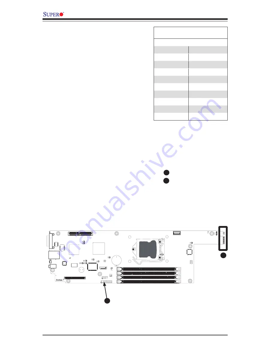
This edge connector, located on the opposite end of the motherboard from the I/O 
back  panel,  is  used  to  connect  the  motherboard  to  the  back  plane  of  the  server 

chassis.  Through this connector, the motherboard will receive its power and com-
municate with the rest of the system (hard drives, warning lamps, etc).

TPM Header
IF + Power

A

B

B

Summary of Contents for X9SCD-F

Page 1: ...USER S MANUAL Revision 1 0b X9SCD F...

Page 2: ...ALLING OR RECOVERING SUCH HARDWARE SOFTWARE OR DATA Any disputes arising between manufacturer and customer shall be governed by the laws of Santa Clara County in the State of California USA The State...

Page 3: ...sec one 10 100 IPMI LAN and a KVM connector on the I O panel This enables the X9SCD F to deliver cost effective microcloud solution in a small form factor package Manual Organization Chapter 1 descri...

Page 4: ...Caution Instructions to be strictly followed to prevent catastrophic system failure or to avoid bodily injury Warning Critical information to prevent damage to the components or data loss Important I...

Page 5: ...Super Micro Computer B V Het Sterrenbeeld 28 5215 ML s Hertogenbosch The Netherlands Tel 31 0 73 6400390 Fax 31 0 73 6416525 Email sales supermicro nl General Information support supermicro nl Technic...

Page 6: ...ith Software 1 10 1 4 Power Configuration Settings 1 11 BIOS Support for USB Keyboard 1 11 Main Switch Override Mechanism 1 11 1 5 Power Supply 1 11 1 6 Super I O 1 12 Chapter 2 Installation 2 1 Stati...

Page 7: ...I2 C Bus to PCI Slots JI2C1 JI2C2 2 17 2 7 Onboard Indicators 2 18 IPMI Dedicated LAN Port 2 18 IPMI Heartbeat LED 2 19 Fail LED 2 19 Unit ID LED 2 19 2 8 Serial ATA and HDD Connections 2 20 SATA Con...

Page 8: ...ppendix B Software Installation Instructions B 1 Installing Drivers B 1 B 2 Configuring SuperDoctor III B 2 Appendix C UEFI BIOS Recovery Instructions An Overview to the UEFI BIOS 1 How to Recover the...

Page 9: ...tmost attention to detail and to provide you with the highest standards in quality and performance Please check that the following items have all been included with your motherboard If anything listed...

Page 10: ...ote All graphics and images shown in this manual were based upon the latest PCB Revision available at the time of publishing of the manual The motherboard you ve received may or may not look exactly t...

Page 11: ...rts and JF1 front panel connections indicates the location of Pin 1 SW1 SW2 JPK1 1 JP2 J4 JKVM1 1 U1 C JTPM1 J2 JPB1 JPG1 JWD1 1 JPME1 1 JPME2 JI2C1 1 B1 JWF1 1 DIMM4 DIMM1 DIMM3 DIMM2 JBT1 1 2ENAB 2...

Page 12: ...F1 1 DIMM4 DIMM1 DIMM3 DIMM2 JBT1 1 2ENAB 2 3DISB 1 2ENAB 2 3DISB 2 3NMI 1 2RST LAN1 USB2 P1 DIMM1A P1 DIMM1B P1 DIMM2A P1 DIMM2B CPU1 USB1 I SATA4 CLEAR CMOS SLOT1 PCI E 3 0 X8 MICRO LP PCI E 3 0 X8...

Page 13: ...0 Micro LP Slot Slot 1 SPKR1 Internal Speaker Buzzer JTPM1 Trusted Platform Module TPM Header JUSB2 USB Header I SATA4 Internal SATA Port JWF1 SATA Disk On Module DOM Power Connector DIMM DIMM Memory...

Page 14: ...orts One 1 I SATA 4 SATA 3 0 Ports Two 2 SATA 0 1 on IF Backpanel USB Devices One 1 Internal USB header for two USB ports and one 1 Internal Type A USB connector Two 2 additional USB ports are availab...

Page 15: ...2 0 support System resource alert via SuperDoctor III SuperDoctor III Watch Dog Unit ID LED System CPU overheat LED CD Utilities BIOS flash upgrade utility Drivers and software for Intel C204 PCH chip...

Page 16: ...x8 SLOT DDR3 CHB DIMM1 DIMM2 Far DIMM1 DIMM2 Far 4 UDIMM MISC VRs 1333 1066MHz 1333 1066MHz 5GT s x4 DMI II 5GT s P11 12 P29 30 LPC RMII VGA KVM RTL8201 PHY HERMON WPCM450 WINBOND PCI32 RJ45 PCIe2 0_...

Page 17: ...isochronous communication providing up to 2 Gb s of software transparent data transfer rate on each read write direction In addition the X9SCD F also features a TCO Time Controlled Operations timer w...

Page 18: ...back on or for it to automatically return to a power on state See the Power Lost Control setting in the BIOS chapter of this manual to change this setting The default set ting is Last State Onboard Vo...

Page 19: ...e suspended and the hard drive will spin down Pressing the power button again will cause the whole system to wake up During the Soft Off state the ATX power supply provides power to keep the required...

Page 20: ...ocessor interrupt system It also provides legacy speed with baud rate of up to 115 2 Kbps as well as an advanced speed with baud rates of 250 K 500 K or 1 Mb s which support higher speed modems The Su...

Page 21: ...its edges only do not touch its components peripheral chips memory modules or gold contacts When handling chips or modules avoid touching their pins Put the motherboard and peripherals back into their...

Page 22: ...because they ground the motherboard to the chassis Make sure that the metal standoffs click in or are screwed in tightly Then use a screwdriver to secure the motherboard onto the motherboard tray Caut...

Page 23: ...all standoffs needed Align the mounting holes on the motherboard against the mounting holes on the motherboard tray Install the motherboard carefully to avoid damaging motherboard compo nents Insert a...

Page 24: ...a Supermicro CSE 938H R1620B 3U chassis The image above shows the X9SCD F and tray on a different angle showing a riser card and a Micro LP network card installed Riser Card Micro LP Network Card The...

Page 25: ...ive CPU Heatsink 1 Do not apply any thermal grease to the heatsink or the CPU die the re quired amount has already been applied 2 Place the heatsink on top of the CPU so that the four mounting holes a...

Page 26: ...quence as shown in the illustration below 2 Gently wriggle the heatsink to loosen it from the CPU Do not use excessive force when wriggling the heatsink 3 Remove the heatsink then remove the CPU from...

Page 27: ...ny possible damage How to Install DDR3 DIMMs 1 Insert the desired number of DIMMs into the memory slots starting with DIMM1A then DIMM2A DIMM1B DIMM2B Pay attention to the notch along the bottom of th...

Page 28: ...emoving DIMMs Position the DIMM module s bottom key so that it aligns with the receptive point on the slot When the module is properlly inserted the Lock Release tabs will automatically secure the DIM...

Page 29: ...er all DIMMs will run at the speed of the slowest DIMM The motherboard will support one DIMM module or three DIMM modules installed For best memory performance install DIMM modules in pairs Recommende...

Page 30: ...anel Connectors and I O Ports 2 4 1 3 1 KVM Port 2 IPMI Port 3 UID Button 4 Power Button and LED Back Panel Connectors SW1 SW2 JPK1 1 JP2 J4 JKVM1 1 U1 C JTPM1 J2 JPB1 JPG1 JWD1 1 JPME1 1 JPME2 JI2C1...

Page 31: ...e cables Power Button LED A Power Button and LED is located right next to the IPMI port Push this button to turn on the motherboard When lit it indicates that this particular motherboard is turned on...

Page 32: ...drives It enables the motherboard to deny access if the TPM associated with the hard drive is not installed in the system See the table on the right for pin definitions Trusted Platform Module Header...

Page 33: ...1 JP2 J4 JKVM1 1 U1 C JTPM1 J2 JPB1 JPG1 JWD1 1 JPME1 1 JPME2 JI2C1 1 B1 JWF1 1 DIMM4 DIMM1 DIMM3 DIMM2 JBT1 1 2ENAB 2 3DISB 1 2ENAB 2 3DISB 2 3NMI 1 2RST LAN1 USB2 P1 DIMM1A P1 DIMM1B P1 DIMM2A P1 D...

Page 34: ...Bus ports USB 2 3 are located on the on the mother board Two of these are available on a header and one on a Type A connector There are also two ports USB 0 1 avail able through the KVM port Cables ar...

Page 35: ...oard jumpers can be used to choose between optional settings Jumpers create shorts between two pins to change the function of the connector Pin 1 is identified with a square solder pad on the printed...

Page 36: ...1 2ENAB 2 3DISB 1 2ENAB 2 3DISB 2 3NMI 1 2RST USB2 P1 DIMM1A P1 DIMM1B P1 DIMM2A P1 DIMM2B CPU1 USB1 I SATA4 CLEAR CMOS SLOT1 PCI E 3 0 X8 PCI E 3 0 X8 Metal contact pads Motherboard SW1 SW2 JPK1 1 JP...

Page 37: ...he table on the right for jumper settings Watch Dog must also be enabled in the BIOS Watch Dog Jumper Settings Jumper Setting Definition Pins 1 2 Reset default Pins 2 3 NMI Open Disabled SMB I2 C Bus...

Page 38: ...ght indicates activity while the green LED on the left indicates the speed of the connection See the tables at right for more information Activity LED Link LED IPMI SW1 SW2 JPK1 1 JP2 J4 JKVM1 1 U1 C...

Page 39: ...MI Heartbeat LED Indicator LED4 LED Settings Blinking IPMI is ready for use B Image rotated 90 Fail LED The Fail LED on LED5 indicates a system failure Please see the table on the right for message de...

Page 40: ...ct cable for each connector Refer to Page 1 1 for cables that came with your shipment I SATA 4 2 0 SATA 0 1 3 0 supported through the IF port A B A B SATA Connections SATA4 One Serial ATA SATA 2 0 con...

Page 41: ...and chas sis 3 Disconnect all ribbon wire cables from the motherboard including those for the keyboard and mouse Also be sure to remove all add on cards 4 Connect the chassis speaker and the power LE...

Page 42: ...the system to lose the CMOS setup information Refer to Section 1 5 for details on recommended power supplies 2 The battery on your motherboard may be old Check to verify that it still supplies 3VDC I...

Page 43: ...rt supermicro com by phone at 408 503 8000 option 2 or by fax at 408 503 8019 3 3 Frequently Asked Questions Question What type of memory does my motherboard support Answer The X9SCD F supports up to...

Page 44: ...he BIOS Then boot the system to the floppy disk The BIOS utility will automatically flash the BIOS without any prompts Please note that this process may take a few minutes to complete Do not be concer...

Page 45: ...the manufacturer the RMA number should be prominently displayed on the outside of the shipping carton and mailed prepaid or hand carried Ship ping and handling charges will be applied for all orders t...

Page 46: ...3 6 X9SCD F User s Manual Notes...

Page 47: ...isplays all the options that can be configured Grayed out options cannot be configured Options in blue can be configured by the user The right frame displays the key legend Above the key legend is an...

Page 48: ...rade the BIOS unless your system has a BIOS related issue Flashing the wrong BIOS can cause irreparable damage to the system In no event shall Supermicro be liable for direct indirect special incident...

Page 49: ...the Tab key or the arrow keys to move between fields The date must be entered in Day MM DD YY format The time is entered in HH MM SS format Note The time is in the 24 hour format For example 5 30 P M...

Page 50: ...n display between POST messages and the OEM logo Select Disabled to display the POST messages Select Enabled to display the OEM logo instead of the normal POST messages The options are Enabled and Dis...

Page 51: ...on is pressed Select 4 Second Override to force the user to press and hold the Power Button for 4 seconds before the system turns off Select Instant Off if you want the system to instanty power off wh...

Page 52: ...e refer to Intel s web site for detailed information Execute Disable Bit Capability Available when supported by the OS and the CPU Set to Enabled to enable the Execute Disable Bit which will allow the...

Page 53: ...C1 C6 C7 and No Limit Turbo Boost Technology Available if Intel EIST technology is Enabled Turbo Mode This feature allows processor cores to run faster than marked frequency in specific conditions Th...

Page 54: ...gs are Enabled and Disabled Active State Power Management Select Enabled to start Active State Power Management for signal transactions between L0 and L1 Links on the PCI Express Bus This maximizes po...

Page 55: ...perating Systems that are not compatible with USB devices The settings are Enabled and Disabled BIOS EHCI Hand Off available if USB Functions above is Enabled This item is for Operating Systems that d...

Page 56: ...SATA drives on the particular SATA port Staggered Spin Up Set this item to Enabled for Staggered Spin up support The options are Enabled and Disabled Hot Plug Set this item to Enabled for hot plugging...

Page 57: ...bled Serial Port 1 Settings This option specifies the base I O port address and the Interrupt Request address of Serial Port 1 Select Auto to allow the serial port to automatically assign system resou...

Page 58: ...lect ANSI VT100 VT100 or VT UTF8 Bits per Second BPS 9600 19200 57600 or 115200 Data Bits 8 or 7 Parity None Even Odd Mark or Space Stop Bits 1 or 2 Flow Control None or Hardware RTS CTS Recorder Mode...

Page 59: ...urations Select Optimal for the onboard fans to run at 30 of the Initial PWM Cycle for best power efficiency and maximum quietness The options are Full Speed 100 of PWM Cycle Standard 50 of PWM Cycle...

Page 60: ...end Mode This setting allows you to configure the ACPI Advanced Configuration and Power Interface sleep state for your system when it is in the Suspend mode The options are Suspend Disabled and S1 POS...

Page 61: ...isabled Erase Event Log This option erases all logged events The options are No Yes Next reset and Yes Every reset When Log is Full This option automatically clears the Event Log memory of all message...

Page 62: ...rm Management Interface IPMI is a set of common interfaces that IT administrators can use to monitor system health and to manage the system as a whole For more information on the IPMI specifications p...

Page 63: ...d Con figuration Protocol Dynamic or manually entered by the user Static If Static is selected the IP Address Subnet Mask and Gateway Address must be manually entered below The options are Static Dyna...

Page 64: ...which devices are boot devices and the order of priority from which the systems boots from during startup Boot Option 1 Boot option 2 Boot Option 3 etc The settings are Built in EFI Shell any detecte...

Page 65: ...ts in the setup Passwords must be at least 3 and up to 20 characters long Administrator Password Press Enter to create a new or change an existing Administrator password User Password Press Enter to c...

Page 66: ...computer so that the new system configuration parameters can take effect Select Save Changes and Exit from the Exit menu and press Enter Discard Changes and Exit Select this option to quit the BIOS Se...

Page 67: ...feature select Save as User Defaults from the Exit menu and press En ter This enables the user to save any changes to the BIOS setup for future use Restore User Defaults To set this feature select Res...

Page 68: ...4 22 X9SCD F User s Manual Notes...

Page 69: ...Beep Codes for recoverable POST errors Recoverable POST Error Beep Codes When a recoverable type of error occurs during POST BIOS will display a POST code that describes the problem BIOS may also issu...

Page 70: ...A 2 X9SCD F User s Manual Notes...

Page 71: ...each item you must re boot the system before proceeding with the next item on the list The bottom icon with a CD on it allows you to view the entire contents of the CD Appendix B Software Installatio...

Page 72: ...lays crucial system information such as CPU temperature system voltages and fan status See the Figure below for a display of the SuperDoctor III interface Note 1 Both default user name and password ar...

Page 73: ...te Control Note SD III Software Revision 1 0 can be downloaded from our web site at ftp ftp supermicro com utility Super_Doctor_III You can also download SDIII User s Guide at http www supermicro com...

Page 74: ...B 4 X9SCD F User s Manual Notes...

Page 75: ...add on card to boot up the system UEFI offers a clean hand off control to a computer system at bootup How to Recover the UEFI BIOS Image the Main BIOS Block An AMIBIOS flash chip consists of a boot se...

Page 76: ...e it to Super ROM for BIOS recovery use 2 Insert the USB device that contains the new BIOS image Super Rom into your USB drive and power on the system 3 While powering on the system keep pressing Ctrl...

Page 77: ...rmware update is completed press any key to reboot the system Flash update progress 47 Note Do not interrupt the process of BIOS flashing until it is completed 6 After the process of BIOS Recovery is...

Page 78: ...eted 9 After seeing the message that BIOS update is completed unplug the AC power cable to clear CMOS and then plug in the AC power cable to power on the system 10 Press Del continuously to enter the...

Page 79: ...expected to result in significant injury or loss of life or catastrophic property damage Accordingly Supermicro disclaims any and all liability and should buyer use or sell such products for use in su...

Reviews: