


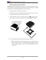


Chapter 2: Installation
2-11
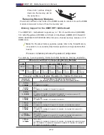
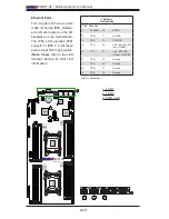
Warning:
Due to insufficient distance (limited clear
-
ance) between memory blocks A & D and B & C, be
sure to put the release tabs of the memory slots in
block D into the upright position before you install
memory modules in block A, and vice versa. Also, be
sure to put the release tabs of the memory slots in
block C into an upright position before installing mem-
ory modules in block B, and vice versa. For example,
put the release tabs of P2-DIMMG1/G2/H1/H2 into an
upright position before installing memory modules into
Slots P1-DIMMA1/A2/B1/B2. Refer to the graphic on
the right for proper memory installation.
X9DRT-HF+
P1 DIMMD2
P1 DIMMD1
Rev. 1.01
1
P2 DIMME1
P2 DIMME2
P2 DIMMF1
P2 DIMMF2
P1 DIMMC1
P1 DIMMC2
P1 DIMMB2
P1 DIMMB1
P1 DIMMA2
P1 DIMMA1
P2 DIMMH2
P2 DIMMH1
P2 DIMMG2
P2 DIMMG1
CPU2
CLOSE 1st
OPEN 1st
CPU1
CLOSE 1st
OPEN 1st
Release Tabs
Notches
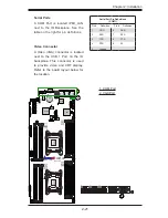
2-4 Installing and Removing the Memory Modules
Note:
Check Supermicro's website for recommended memory modules.
CAUTION
Exercise extreme care when installing or removing DIMM
modules to prevent any possible damage.
Installing & Removing DIMMs
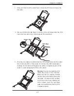
1. Insert the desired number of DIMMs into the memory slots, starting with P1-
DIMMA1. Push the release tabs outwards on both ends of the DIMM slot to
unlock it.
2. Align the key of the DIMM module with the receptive point on the memory
slot.
3. Align the notches on both ends of the module against the receptive points on
the ends of the slot.
4. Use two thumbs together to press the notches on both ends of the module
straight down into the slot until the module snaps into place.
5. Press the release tabs to the locking positions to secure the DIMM module
into the slot.
Limited
Clearance
D
C
B
A