


2-36
X9DR7-LN4F/X9DR7-LN4F-JBOD/X9DRE-LN4F Motherboard User’s Manual
DM1
JPG1
JBT1
J2
1
JTPM
1
JIPMB1
FA
NB
FAN4
FAN2
FAN1
JI2C
1
JI2C
2
JBAT1
JSD1
J2
2
JPW2
JPI2C1
JD
1
JF1
X9DR7/E-LN4F
Rev. 1.00
CPU2 SLOT3 PCI-E 3.0 X1
6
L-SAS 4~7
CPU2 SLOT4 PCI-E 3.0 X8
CPU1 SLOT1 PCI-E 3.0 X8
XDP-CPU
CPU1 SLOT2 PCI-E 3.0 X8
I-S
AT
A0
COM2
USB4/5
S-SA
TA
2
S-SA
TA
0
CPU1 SLOT6 PCI-E 3.0 X8
CPU2 SLOT5 PCI-E 3.0 X1
6
L-SAS 0~3
P1 DIMMC
1
P1 DIMMC
2
P1 DIMMD
1
P1 DIMMD
2
P1 DIMMB
2
P1 DIMMB
1
P2 DIMME
1
P2 DIMME2
P1 DIMMA
2
P2 DIMMF
1
P1 DIMMA
1
P2 DIMMF
2
P2 DIMMH
2
P2 DIMMH
1
P2 DIMMG1
P2 DIMMG
2
JPWR
1
LE1
T-SGPIO2
BMC
CTRL
CTRL
LAN
PCH
CTRL
SAS
SP1
FAN3
FANA
JF2
JOH
1
JW
D
JSTBY1
JS
7
JS
6
JL
1
JS6
JS
5
S-SA
TA
1
S-SA
TA
3
T-SGPIO1
I-S
AT
A3
I-S
AT
A2
I-S
AT
A1
I-S
AT
A4
I-S
AT
A5
BIOS
SCU-SGPIO1
USB6
J23
J25
JPB1
J3
0
J2
9
JPL1
FAN5
Battery
JPWR
2
LAN2/4
LAN1/3
USB2&3
USB0&1
IPMI_LAN
KB/Mouse
COM1
VGA
FA
N6
JPME
2
JPME1
CPU1
CLOSE 1st
OPEN 1st
CPU2
CLOSE 1st
OPEN 1st
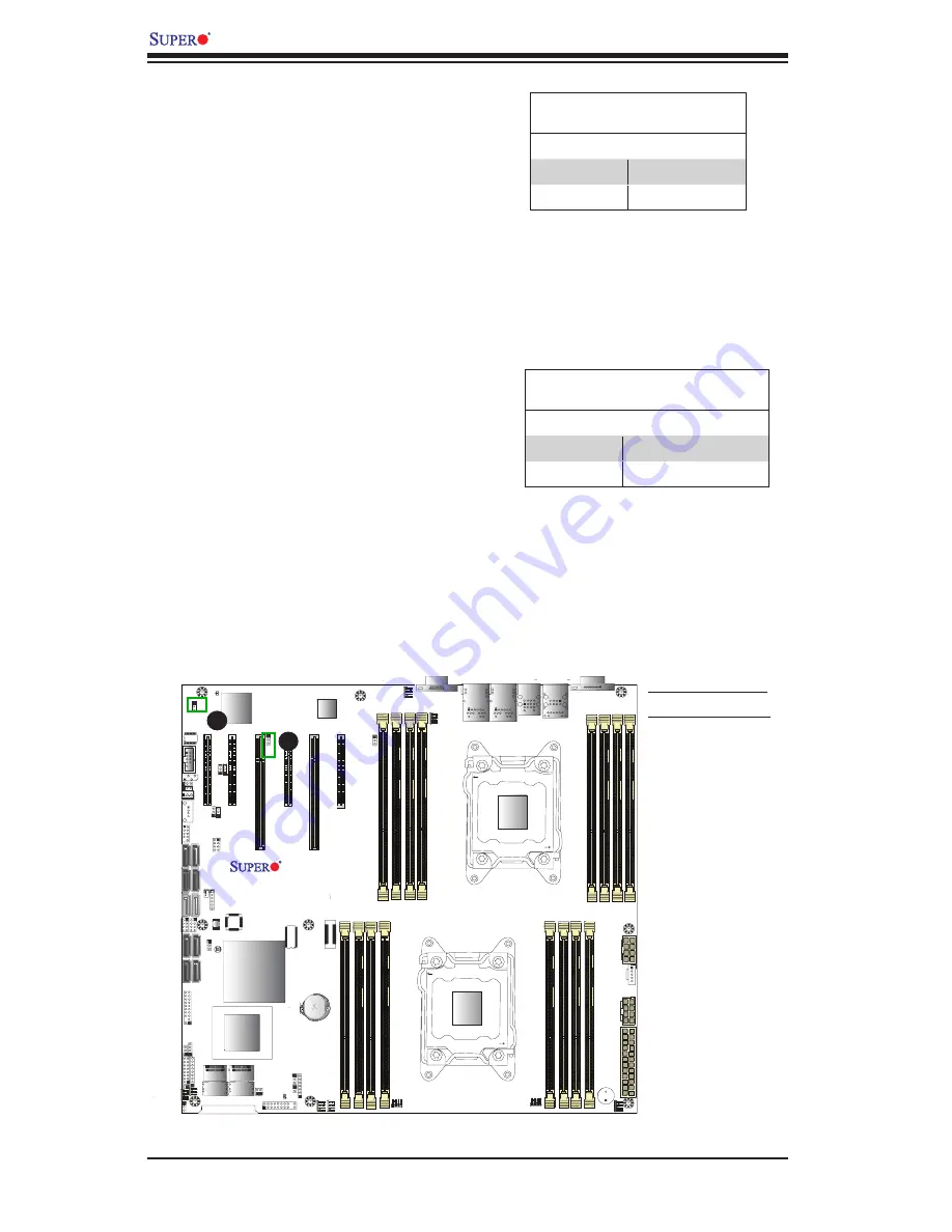
A.
VGA Enabled
B.
BMC Enabled
A
B
VGA Enable
Jumper JPG1 allows the user to enable
the onboard VGA connector. The default
setting is 1-2 to enable the connection.
See the table on the right for jumper
settings.
VGA Enable
Jumper Settings
Jumper Setting Definition
1-2
Enabled (Default)
2-3
Disabled
BMC Enable
Jumper JPB1 allows you to enable the
embedded WPCM450R BMC (Base-
board Management) Controller to pro-
vide IPMI 2.0/KVM support on the
motherboard. See the table on the right
for jumper settings.
BMC Enable
Jumper Settings
Jumper Setting Definition
Pins 1-2
BMC Enable (Default)
Pins 2-3
Disable
Summary of Contents for X9DR7-LN4F
Page 1: ...USER S MANUAL Revision 1 1 X9DRE LN4F X9DR7 LN4F JBOD X9DR7 LN4F...
Page 66: ...2 42 X9DR7 LN4F X9DR7 LN4F JBOD X9DRE LN4F Motherboard User s Manual Notes...
Page 108: ...A 2 X9DR7 LN4F X9DR7 LN4F JBOD X9DRE LN4F Motherboard User s Manual Notes...
Page 112: ...B 4 X9DR7 LN4F X9DR7 LN4F JBOD X9DRE LN4F Motherboard User s Manual Notes...


