background image

Chapter 2: Installation

2-13

T-

SGPIO1

3-SGPIO1

3-SGPIO2

T-

SGPIO2

I-S

AT

A5

I-S

AT

A4

I-S

AT

A3

I-S

AT

A2

I-S

AT

A1

I-S

AT

A0

JPTM1

SAS0

SAS1

SAS2

SAS3

JUSB1617

9

2

1

JFPAUDIO

JSTBY

1

3

B8

1

B8

2

A8

1

A8

2

PCIE4

JPCI3

JWF1

1

3

JC

OM
2

1

5

6

JC

OM
1

JUSB8

9

JUSB1011

1

7

JUSB1213

1

CPU1

JUSB45

JUSB2

3

JKBMS_USB0

1

JAUDIO1

JLAN2_USB67

BT1

+

PCIE1

PCIE2

DIMM2A

DIMM3

A

DIMM4

A

DIMM1B

DIMM2B

DIMM3

B

DIMM4

B

DIMM1A

JF

1

JD1

JTAG1

6

1

REV
:1.01

Te

sted to 

Co
mpl

y

Wi
th FC

C Standard

s

FOR HOME OR OFFICE US

E

DESIGNED IN US

A

MA
C

SAS C

ODE

BAR C

ODE

JPW2

PCIE6

1

JPI2C1

JBT1

JPW1

1

JSPDIF_OUT

1

JSPDIF_IN

JI2C2

1

JI2C1

1

1

JL1

1

JCF1

1

JOH1

DP2

3

1

JP

ME
1

JPAC1

JWD1

JVR2

JPL2

JPUSB1

JP

ME_DBG

4

FANA

FAN3

FAN1

FAN2

FAN4

MH3

MH7

MH4

MH8

MH1

MH9

MH6

MH5

Pin1:RAID_KEY_PCH

JRK1

Pin2:Ground
Pin3:PCH_DYN_SKU

:TPM/PRO80

OF

F:

By BIOS

JF

PA

UDIO_EN1

ON:F

orce Enable

USB3.0 2/

3

2-3:Normal

1-2:BIOS recovery

JPBIOS1

JPME_DBG
1-2:ME Debug
2-3:Normal
JPME1
1-2:ME recovery

2-3:Normal

SL

OT

6 PCI-E 3.0 X16

SL

OT

4 PCI-E 3.0 X16

SL

OT

2 PCI-E 3.0 X4(IN X8)

SL

OT

1 PCI-E 2.0 X4(IN X8)

1-2:ENABLE

2-3:DISABLE

JPT1

USB12/13

USB10/11

COM1

1-2:ENABLE

JPAC1:AUDIO

2-3:DISABLE

AU
DIO FP

HD AUDIO

USB6/7

USB3.0 0/1

USB2/3

USB0/1

X9SR

A

1-2 ENable

Power

Flash

KB/MOUSE

JPUSB1:USB 

Wa
ke Up

2-3 Disabl

e

PWRI2

C

JF

1

RS

T

ON PW

R

PW
R

FF

FA

IL

HD
D

NIC

1

2

NIC

OH

LE

D

NM
I

PW
R

X

PWR LED

SPEAKER

1-3:

4-7:

JD1:

2-3:NMI

JWD1:Watch Dog

1-2:RST

LAN1

LAN2

USB4/5

INTRUSION

    CHASSIS

OFF: SLAVE

ON: MASTER

JCF1:Compact Flash

Compact

USB8/9

 Wake on Lan

COM2

OFF
:DISABLE

ON: ENABLE I2C bus 

fo

r PCI slot

JI2C1/JI2C

2

SL

OT

5 PCI-E 2.0 X1

SL

OT

3 PCI 33MHZ

CLOSE 1st

OPEN 1st

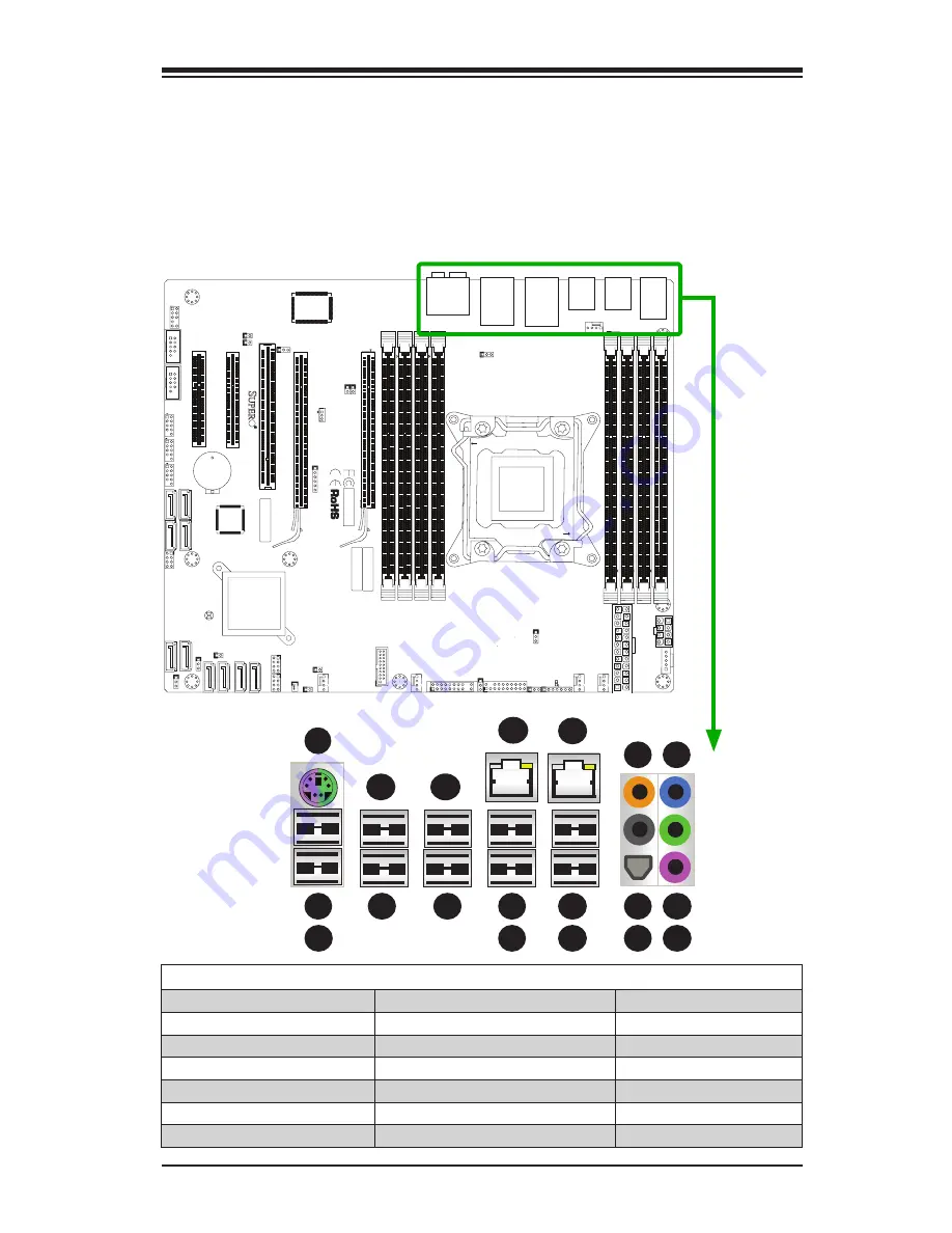
2-5  Connectors/IO Ports

The I/O ports are color coded in conformance with the industry standards. See the 
figure below for the colors and locations of the various I/O ports.

Motherboard I/O Backpanel

1

1

2

1

3

1

4

1

5

1

6

1

7

1

8

1

9

Motherboard I/O Backpanel 

1. Keyboard/Mouse

7. USB 2.0 Port 5

13. USB 2.0 Port 7

2. USB 2.0 Port 0

8. LAN 1 Port

14. Center/LFE Out

3. USB 2.0 Port 1

9. USB 3.0 Port 0

15. Surround Out 

4. USB 2.0 Port 2

10. USB 3.0 Port 1

16. S/P DIF Out

5. USB 2.0 Port 3

11. LAN 2 Port

17. Line In

6. USB 2.0 Port 4

12. USB 2.0 Port 6

18. Line Out
19. Mic In

1

10

1

11

1

12

1

13

1

14

1

15

1

16

1

17

1

18

1

19

Summary of Contents for Supero X9SRA

Page 1: ...USER S MANUAL Revision 1 1 X9SRA...

Page 2: ...ING OR RECOVERING SUCH HARDWARE SOFTWARE OR DATA Any disputes arising between manufacturer and customer shall be governed by the laws of Santa Clara County in the State of California USA The State of...

Page 3: ...cro com products for processor and memory support updates This product is intended to be installed and serviced by professional technicians Manual Organization Chapter 1 describes the features specifi...

Page 4: ...rictly followed to prevent catastrophic system failure or to avoid bodily injury Warning Critical information to prevent damage to the components or data loss Important Important information given to...

Page 5: ...r Micro Computer B V Het Sterrenbeeld 28 5215 ML s Hertogenbosch The Netherlands Tel 31 0 73 6400390 Fax 31 0 73 6416525 Email sales supermicro nl General Information support supermicro nl Technical S...

Page 6: ...ing a Passive CPU Heatsink 2 6 Removing the Heatsink 2 7 2 3 Installing DDR3 Memory 2 8 DIMM Installation 2 8 Removing Memory Modules 2 8 Memory Support 2 9 Memory Population Guidelines 2 10 2 4 Mothe...

Page 7: ...IO 1 2 3 SGPIO 1 2 Headers 2 25 TPM Header JTPM1 2 25 Overheat Fan Fail LED JOH1 2 26 Serial Ports 2 27 Front Accessible Audio Header 2 27 SPDIF IN SPDIF OUT JSPDIF_IN JSPDIF_OUT 2 28 2 7 Jumper Setti...

Page 8: ...urations 4 4 4 4 Event Logs 4 20 4 5 Security Settings 4 22 4 6 Boot 4 23 4 7 Save Exit 4 24 Appendix A BIOS Error Beep Codes A 1 BIOS Error Beep Codes A 1 Appendix B Software Installation Instruction...

Page 9: ...utmost attention to detail to provide you with the highest standards in quality and performance Please check that the following items have all been included with your motherboard If anything listed he...

Page 10: ...All graphics shown in this manual were based upon the latest PCB Revision available at the time of publishing of the manual The motherboard you ve received may or may not look exactly the same as the...

Page 11: ...1 1 JL1 1 JCF1 1 JOH1 DP2 3 1 JPME1 JPAC1 JWD1 JVR2 JPL2 JPUSB1 JPME_DBG 4 FANA FAN3 FAN1 FAN2 FAN4 MH3 MH7 MH4 MH8 MH1 MH9 MH6 MH5 Pin1 RAID_KEY_PCH JRK1 Pin2 Ground Pin3 PCH_DYN_SKU TPM PRO80 OFF B...

Page 12: ...0 0 1 USB2 3 USB0 1 X9SRA 1 2 ENable Power Flash KB MOUSE JPUSB1 USB Wake Up 2 3 Disable PWRI2C JF1 RST ON PWR PWR FF FAIL HDD NIC 1 2 NIC OH LED NMI PWR X PWR LED SPEAKER 1 3 4 7 JD1 2 3 NMI JWD1 Wa...

Page 13: ...ral Purpose I O Headers for SAS SATA0 3 Serial ATA ports SATA 2 0 3Gb s I SATA0 I SATA1 Serial ATA ports SATA 3 0 6Gb s I SATA2 5 Serial ATA ports SATA 2 0 3Gb s JWF1 SATA DOM Disk On Module Power Con...

Page 14: ...n x8 Slot One 1 PCI 33MHz Slot Network Connections Integrated LAN One 1 Intel 82579LM and One 1 Intel 82574L Gb LAN I O Devices SATA Connections SATA 2 0 Ports Four 4 3 Gb s RAID 0 1 10 via SCU SATA 2...

Page 15: ...Stdby VBAT HT Memory Chipset CPU 6 phase switching voltage regulator CPU System overheat LED and control CPU Thermal Trip support CPU Chassis Environment Monitor Fan Control Fan status monitoring with...

Page 16: ...4 G3 0 4 0 3 5 SLOT 5 0 2 PCI E X1 G2 PCI E X1 0 8 0 7 uPD720200 0 6 LAN1 82579 PCI E X1 G2 PCI E X1 G2 6 7 LAN2 82574 PCI E X1 G2 8 RJ45 RJ45 USB 3 0 14 15 1 2 3 4 6 7 COM2 Header SLOT 4 USB 2 0 6 0...

Page 17: ...equire ments for Intel Xeon platforms Intel C600 Chipset Features Direct Media Interface up 5 Gt s transfer Full Duplex Intel Matrix Storage Technology and Intel Rapid Storage Technology Intel I O Vir...

Page 18: ...is sent to the screen The user can adjust the voltage thresholds to define the sensitivity of the voltage monitor Fan Status Monitor with Firmware Control PC health monitoring in the BIOS can check t...

Page 19: ...independent implementation that is compatible with Windows XP Windows Vista and Windows 2008 Operating Systems Slow Blinking LED for Suspend State Indicator When the CPU goes into a suspend state the...

Page 20: ...tall a power surge protector to help avoid problems caused by power surges 1 7 Super I O The Super I O supports two high speed 16550 compatible serial communication ports UARTs Each UART includes a 16...

Page 21: ...edges only do not touch its components peripheral chips memory modules or gold contacts When handling chips or modules avoid touching their pins Put the motherboard and peripherals back into their ant...

Page 22: ...y make sure that you use an Intel certified multi directional heatsink only Make sure to install the system board into the chassis before you install the CPU heatsink When receiving a server board wit...

Page 23: ...locking position 3 With the Close 1st lever fully retracted gently push down on the Open 1st lever to open the load plate Lift the load plate to open it completely OPEN1st WARNING OPEN1st WARNING 1 2...

Page 24: ...on its edges Align the CPU keys semi circle cutouts against the socket keys Socket Keys CPU Keys Warning You can only in stall the CPU inside the socket in one direction Make sure that it is properly...

Page 25: ...or the socket 5 With the CPU inside the socket inspect the four corners of the CPU to make sure that the CPU is properly installed 6 To close and lock the socket close the load plate with the CPU Loc...

Page 26: ...t has already been applied 2 Place the heatsink on top of the CPU so that the four mounting holes are aligned with those on the Motherboard s and the Heatsink Bracket under neath 3 Screw in two diagon...

Page 27: ...from the motherboard in the sequence as shown in the illustration below 2 Gently wriggle the heatsink to loosen it from the CPU Do not use excessive force when wriggling the heatsink 3 Once the CPU i...

Page 28: ...SAS3 JUSB1617 9 2 1 JFPAUDIO JSTBY 1 3 B81 B82 A81 A82 PCIE4 JPCI3 JWF1 1 3 JCOM2 1 5 6 JCOM1 JUSB89 JUSB1011 1 7 JUSB1213 1 CPU1 JUSB45 JUSB23 JKBMS_USB01 JAUDIO1 JLAN2_USB67 BT1 PCIE1 PCIE2 DIMM2A D...

Page 29: ...dards FOR HOME OR OFFICE USE DESIGNED IN USA MAC SAS CODE BAR CODE JPW2 PCIE6 1 JPI2C1 JBT1 JPW1 1 JSPDIF_OUT 1 JSPDIF_IN JI2C2 1 JI2C1 1 1 JL1 1 JCF1 1 JOH1 DP2 3 1 JPME1 JPAC1 JWD1 JVR2 JPL2 JPUSB1...

Page 30: ...DIMM4A DIMM1B DIMM2B DIMM3B DIMM4B Total System Memory 2GB 2GB 4GB 2GB 2GB 2GB 2GB 8GB 2GB 2GB 2GB 2GB 2GB 2GB 12GB 2GB 2GB 2GB 2GB 2GB 2GB 2GB 2GB 16GB 4GB 4GB 8GB 4GB 4GB 4GB 4GB 16GB 4GB 4GB 4GB 4G...

Page 31: ...nable USB3 0 2 3 2 3 Normal 1 2 BIOS recovery JPBIOS1 JPME_DBG 1 2 ME Debug 2 3 Normal JPME1 1 2 ME recovery 2 3 Normal SLOT6 PCI E 3 0 X16 SLOT4 PCI E 3 0 X16 SLOT2 PCI E 3 0 X4 IN X8 SLOT1 PCI E 2 0...

Page 32: ...in the chassis as needed 5 Install the motherboard into the chassis carefully to avoid damaging mother board components 6 Using the Philips screwdriver insert a Pan head 6 screw into a mounting hole o...

Page 33: ...N X8 SLOT1 PCI E 2 0 X4 IN X8 1 2 ENABLE 2 3 DISABLE JPT1 USB12 13 USB10 11 COM1 1 2 ENABLE JPAC1 AUDIO 2 3 DISABLE AUDIO FP HD AUDIO USB6 7 USB3 0 0 1 USB2 3 USB0 1 X9SRA 1 2 ENable Power Flash KB MO...

Page 34: ...current limit A Backpanel USB 2 0 1 B Backpanel USB 2 0 0 C PS2 Keyboard Mouse Keyboard Mouse For a keyboard cable or Mouse cable optional Back Panel USB 2 0 Port 0 For a Y cable that connects to a K...

Page 35: ...lash Compact USB8 9 Wake on Lan COM2 OFF DISABLE ON ENABLE I2C bus for PCI slot JI2C1 JI2C2 SLOT5 PCI E 2 0 X1 SLOT3 PCI 33MHZ CLOSE 1st OPEN 1st 1 Back Panel USB 2 0 USB 0 2 Back Panel USB 2 0 USB 1...

Page 36: ...Connection 1 LAN1 2 LAN2 1 1 1 2 1 3 1 4 1 5 1 6 1 7 1 8 3 Center LFE Out 4 Surround Out 5 S P DIF Out 6 Line In 7 Line Out 8 Mic In Back_Panel High Definition Audio HD Audio This motherboard feature...

Page 37: ...CI E 2 0 X4 IN X8 1 2 ENABLE 2 3 DISABLE JPT1 USB12 13 USB10 11 COM1 1 2 ENABLE JPAC1 AUDIO 2 3 DISABLE AUDIO FP HD AUDIO USB6 7 USB3 0 0 1 USB2 3 USB0 1 X9SRA 1 2 ENable Power Flash KB MOUSE JPUSB1 U...

Page 38: ...ns Power LED Pin Definitions JF1 Pin Definition 15 LED VCC 16 Ground A PWR LED B HDD LED C PWR Fail LED A B HDD LED The HDD LED connection is located on pins 13 and 14 of JF1 Attach a cable here to in...

Page 39: ...C 10 12 Ground C A NIC1 LED B NIC2 LED C OH Fan Fail UID LED OH Fan Fail LED Pin Definitions JF1 Pin Definition 7 LED VCC 8 OH Fan Fail LED OH Fan Fail Indicator Status State Definition Off Normal On...

Page 40: ...n off the power in the suspend mode press the button for at least 4 seconds Refer to the table on the right for pin definitions Power Button Pin Definitions JF1 Pin Definition 1 Signal 2 3V Standby Re...

Page 41: ...1 X9SRA 1 2 ENable Power Flash KB MOUSE JPUSB1 USB Wake Up 2 3 Disable PWRI2C JF1 RST ON PWR PWR FF FAIL HDD NIC 1 2 NIC OH LED NMI PWR X PWR LED SPEAKER 1 3 4 7 JD1 2 3 NMI JWD1 Watch Dog 1 2 RST LA...

Page 42: ...FANA FAN3 FAN1 FAN2 FAN4 MH3 MH7 MH4 MH8 MH1 MH9 MH6 MH5 Pin1 RAID_KEY_PCH JRK1 Pin2 Ground Pin3 PCH_DYN_SKU TPM PRO80 OFF By BIOS JFPAUDIO_EN1 ON Force Enable USB3 0 2 3 2 3 Normal 1 2 BIOS recovery...

Page 43: ...JPAC1 AUDIO 2 3 DISABLE AUDIO FP HD AUDIO USB6 7 USB3 0 0 1 USB2 3 USB0 1 X9SRA 1 2 ENable Power Flash KB MOUSE JPUSB1 USB Wake Up 2 3 Disable PWRI2C JF1 RST ON PWR PWR FF FAIL HDD NIC 1 2 NIC OH LED...

Page 44: ...N1 FAN2 FAN4 MH3 MH7 MH4 MH8 MH1 MH9 MH6 MH5 Pin1 RAID_KEY_PCH JRK1 Pin2 Ground Pin3 PCH_DYN_SKU TPM PRO80 OFF By BIOS JFPAUDIO_EN1 ON Force Enable USB3 0 2 3 2 3 Normal 1 2 BIOS recovery JPBIOS1 JPME...

Page 45: ...3 4 7 JD1 2 3 NMI JWD1 Watch Dog 1 2 RST LAN1 LAN2 USB4 5 INTRUSION CHASSIS OFF SLAVE ON MASTER JCF1 Compact Flash Compact USB8 9 Wake on Lan COM2 OFF DISABLE ON ENABLE I2C bus for PCI slot JI2C1 JI2...

Page 46: ...E_DBG 1 2 ME Debug 2 3 Normal JPME1 1 2 ME recovery 2 3 Normal SLOT6 PCI E 3 0 X16 SLOT4 PCI E 3 0 X16 SLOT2 PCI E 3 0 X4 IN X8 SLOT1 PCI E 2 0 X4 IN X8 1 2 ENABLE 2 3 DISABLE JPT1 USB12 13 USB10 11 C...

Page 47: ...Y_PCH JRK1 Pin2 Ground Pin3 PCH_DYN_SKU TPM PRO80 OFF By BIOS JFPAUDIO_EN1 ON Force Enable USB3 0 2 3 2 3 Normal 1 2 BIOS recovery JPBIOS1 JPME_DBG 1 2 ME Debug 2 3 Normal JPME1 1 2 ME recovery 2 3 No...

Page 48: ...JPBIOS1 JPME_DBG 1 2 ME Debug 2 3 Normal JPME1 1 2 ME recovery 2 3 Normal SLOT6 PCI E 3 0 X16 SLOT4 PCI E 3 0 X16 SLOT2 PCI E 3 0 X4 IN X8 SLOT1 PCI E 2 0 X4 IN X8 1 2 ENABLE 2 3 DISABLE JPT1 USB12 1...

Page 49: ...2 ENABLE 2 3 DISABLE JPT1 USB12 13 USB10 11 COM1 1 2 ENABLE JPAC1 AUDIO 2 3 DISABLE AUDIO FP HD AUDIO USB6 7 USB3 0 0 1 USB2 3 USB0 1 X9SRA 1 2 ENable Power Flash KB MOUSE JPUSB1 USB Wake Up 2 3 Disa...

Page 50: ...ENABLE JPAC1 AUDIO 2 3 DISABLE AUDIO FP HD AUDIO USB6 7 USB3 0 0 1 USB2 3 USB0 1 X9SRA 1 2 ENable Power Flash KB MOUSE JPUSB1 USB Wake Up 2 3 Disable PWRI2C JF1 RST ON PWR PWR FF FAIL HDD NIC 1 2 NIC...

Page 51: ...2C JF1 RST ON PWR PWR FF FAIL HDD NIC 1 2 NIC OH LED NMI PWR X PWR LED SPEAKER 1 3 4 7 JD1 2 3 NMI JWD1 Watch Dog 1 2 RST LAN1 LAN2 USB4 5 INTRUSION CHASSIS OFF SLAVE ON MASTER JCF1 Compact Flash Comp...

Page 52: ...KU TPM PRO80 OFF By BIOS JFPAUDIO_EN1 ON Force Enable USB3 0 2 3 2 3 Normal 1 2 BIOS recovery JPBIOS1 JPME_DBG 1 2 ME Debug 2 3 Normal JPME1 1 2 ME recovery 2 3 Normal SLOT6 PCI E 3 0 X16 SLOT4 PCI E...

Page 53: ...X8 SLOT1 PCI E 2 0 X4 IN X8 1 2 ENABLE 2 3 DISABLE JPT1 USB12 13 USB10 11 COM1 1 2 ENABLE JPAC1 AUDIO 2 3 DISABLE AUDIO FP HD AUDIO USB6 7 USB3 0 0 1 USB2 3 USB0 1 X9SRA 1 2 ENable Power Flash KB MOU...

Page 54: ...COM1 1 2 ENABLE JPAC1 AUDIO 2 3 DISABLE AUDIO FP HD AUDIO USB6 7 USB3 0 0 1 USB2 3 USB0 1 X9SRA 1 2 ENable Power Flash KB MOUSE JPUSB1 USB Wake Up 2 3 Disable PWRI2C JF1 RST ON PWR PWR FF FAIL HDD NIC...

Page 55: ...E 3 0 X16 SLOT2 PCI E 3 0 X4 IN X8 SLOT1 PCI E 2 0 X4 IN X8 1 2 ENABLE 2 3 DISABLE JPT1 USB12 13 USB10 11 COM1 1 2 ENABLE JPAC1 AUDIO 2 3 DISABLE AUDIO FP HD AUDIO USB6 7 USB3 0 0 1 USB2 3 USB0 1 X9S...

Page 56: ...2 36 X9SRA Motherboard Series User s Manual Notes...

Page 57: ...2 Make sure that there are no short circuits between the motherboard and chassis 3 Disconnect all ribbon wire cables from the motherboard including those for the keyboard and mouse Also be sure to re...

Page 58: ...t you use the memory modules of the same type and speed for all DIMMs in the system Do not use memory modules of differ ent sizes different speeds and different types on the same motherboard 3 Check f...

Page 59: ...be downloaded from our website at http www supermi cro com support bios Note Not all BIOS can be flashed Some cannot be flashed it depends on the boot block code of the BIOS 3 If you ve followed the i...

Page 60: ...between ami bat and the filename The BIOS ROM filename will bear the motherboard name i e X9SRA and build version as the extension For example X9SRA1 218 When completed your system will automatically...

Page 61: ...ppy drive instead of the onboard floppy drive For the IPMI jumper location please check Chapter 1 Question What is the heatsink part number for my X9SRA motherboard series Answer The recommended heats...

Page 62: ...e battery s polarity The positive side should be facing up 3 Insert the battery into the battery holder and push it down until you hear a click to ensure that the battery is securely locked Warning Wh...

Page 63: ...upermicro com RmaForm When you return the motherboard to the manufacturer the RMA number should be prominently displayed on the outside of the shipping carton and mailed prepaid or hand carried Shippi...

Page 64: ...3 8 X9SRA Motherboard Series User s Manual Notes...

Page 65: ...e displays all the options that can be configured Grayed out options cannot be configured Options in blue can be configured by the user The right frame displays the key legend Above the key legend is...

Page 66: ...mages arising from a BIOS update If you have to update the BIOS do not shut down or reset the system while the BIOS is updating This is to avoid possible boot failure 4 2 Main Setup When you first ent...

Page 67: ...em Time or Sys tem Date using the arrow keys Enter new values through the keyboard Press the Tab key or the arrow keys to move between fields The date must be entered in Day MM DD YY format The time i...

Page 68: ...it For F1 If Error This forces the system to wait until the F1 key is pressed if an error occurs The options are Disabled and Enabled Interrupt 19 Capture Interrupt 19 is the software interrupt that h...

Page 69: ...ure to set the power state after a power outage Select Stay Off for the system power to remain off after a power loss Select Power On for the system power to be turned on after a power loss Select Las...

Page 70: ...nabled to use the processor s Advanced Encryption Standard AES feature The options are Enabled and Disabled Hardware Prefetcher Available when supported by the CPU If set to Enabled the hardware pre f...

Page 71: ...information The options are Disabled and Enabled Turbo Mode This feature allows processor cores to run faster than marked frequency in specific conditions The options are Disabled and Enabled C1E Sup...

Page 72: ...with greater reliabil ity security and availability in networking and data sharing The settings are Enabled and Disabled Intel I OAT The Intel I OAT I O Acceleration Technology significantly reduces...

Page 73: ...rigger fail over The spare memory is put online and used as active memory in place of the failed memory DRAM RAPL Mode RAPL which stands for Running Average Power Limit is a feature that provides mech...

Page 74: ...d the read data from memory turns out to be a correctable error the error is corrected and sent to the requestor the original source Memory is updated as well Select Enabled to use Demand Scrubbing fo...

Page 75: ...imed by the EHCI driver The settings are Enabled and Disabled GbE Controller Select Enabled to activate the onboard gigabit Ethernet controller The settings are Enabled and Disabled Wake on LAN from S...

Page 76: ...Enhanced AHCI Mode The following items are displayed when AHCI Mode is selected Aggressive Link Power Management This feature Enables or Disables Agressive Link Power Management support for Cougar Poi...

Page 77: ...OM PCI Latency Timer This feature sets the latency Timer of each PCI device installed on a PCI bus Se lect 64 to set the PCI latency to 64 PCI clock cycles The options are 32 PCI Bus Clocks 64 PCI Bus...

Page 78: ...LAN Option ROM Select This feature selects whether to load the iSCSI or PXE onboard LAN option ROM The options are iSCSI and PXE Load Onboard LAN1 Option ROM Load Onboard LAN2 Option ROM This feature...

Page 79: ...0 11 12 IO 2E8h IRQ 3 4 5 6 7 9 10 11 12 The options for Serial Port 2 are Auto IO 2F8h IRQ 3 IO 3F8h IRQ 3 4 5 6 7 9 10 11 12 IO 2F8h IRQ 3 4 5 6 7 9 10 11 12 IO 3E8h IRQ 3 4 5 6 7 9 10 11 12 IO 2E8h...

Page 80: ...Band Manage ment Windows Emergency Management Services EMS ports The options are Enabled and Disabled Console Redirection Settings Configure the following options for the Console Redirection Settings...

Page 81: ...ered as the normal operating state The CPU temperature is well below the CPU Temperature Tolerance The mother board fans and CPU will run normally as configured in the BIOS Fan Speed Control User inte...

Page 82: ...e in these options High Precision Event Timer Select Enabled to activate the High Performance Event Timer HPET that produces periodic interrupts at a much higher frequency than a Real time Clock RTC d...

Page 83: ...tatus Intel TXT LT SX Configuration Intel TXT Initialization Intel TXT Trusted Execution Technology helps protect against software based at tacks and ensures protection confidentiality and integrity o...

Page 84: ...s Smbios Event Log Change this item to enable or disable all features of the Smbios Event Log ging during boot The options are Enabled and Disabled Runtime Error Logging Support Change this item to en...

Page 85: ...bled The options are Disabled and Enabled MECI The Multiple Event Count Increment MECI counter counts the number of occurences a duplicate event must happen before the MECI counter is incre mented Thi...

Page 86: ...n existing User password BIOS SETUP UTILTY Select Screen Select Item Enter Select Change Opt F1 General Help F2 Previous Values F3 Optimized Defaults F4 Save Exit ESC Exit Version x xx xxxx Copyright...

Page 87: ...Add New Boot Option Delete Boot Option This feature allows the user to delete a previously defined boot device from which the systems boots from during startup Boot Option 1 Boot option 2 Boot Option...

Page 88: ...this option to save any changes made This will not reset reboot the system Discard Changes Select this option and press Enter to discard all the changes and return to the AMI BIOS Utility Program Rest...

Page 89: ...etup for future use Restore User Defaults To set this feature select Restore User Defaults from the Exit menu and press En ter Use this feature to retrieve user defined settings that were saved previo...

Page 90: ...4 26 X9SRA Motherboard Series User s Manual Notes...

Page 91: ...rror oc curs you should consult with your system manufacturer for possible repairs These fatal errors are usually communicated through a series of audible beeps The numbers on the fatal error list cor...

Page 92: ...A 2 X9SRA Motherboard Series User s Manual Notes...

Page 93: ...diskette by booting into a Driver CD please set the SATA Configuration to Compatible Mode and configure SATA as IDE in the BIOS Setup After making the driver diskette be sure to change the SATA setti...

Page 94: ...or III displays crucial system information such as CPU temperature system voltages and fan status See the Figure below for a display of the SuperDoctor III interface Note 1 The default user name and p...

Page 95: ...lay Screen II Remote Control Note The SuperDoctor III software and manual can be downloaded from our Website at http www supermicro com products accessories software SuperDoctorIII cfm For Linux we st...

Page 96: ...B 4 X9SRA Motherboard Series User s Manual Notes...

Page 97: ...ntrol to a computer system at bootup How to Recover the UEFI BIOS Image the Main BIOS Block An AMIBIOS flash chip consists of a boot sector block and a main BIOS code block a main BIOS image The boot...

Page 98: ...at contains the new BIOS image Super Rom into your USB drive and power on the system 3 While powering on the system keep pressing Ctrl and Home simultane ously on your PS2 or USB keyboard until your h...

Page 99: ...eboot the system Flash update progress 47 7 Using a different system extract the BIOS package into a bootable USB flash drive 8 When a DOS prompt appears type AMI BAT BIOSname at the prompt Note Do no...

Page 100: ...eted unplug the AC power cable to clear CMOS and then plug in the AC power cable to power on the system 10 Press Del continuously to enter the BIOS Setup utility 11 Press F3 to load default settings 1...

Page 101: ...expected to result in significant injury or loss of life or catastrophic property damage Accordingly Supermicro disclaims any and all liability and should buyer use or sell such products for use in su...

Reviews: