Supero SUPERO X8DTG-QF User Manual Download Page 28

2-8


X8DTG-QF User's Manual

Memory Support

The X8DTG-QF supports up to 192 GB* of Registered ECC or up to 48 GB of Unbuf-

fered ECC/Non-ECC DDR3 1333/1066/800 MHz Memory in 12 DIMMs. (*Refer to 

our memory recommendation list posted on our website at www.supermicro.com.)


Note1:

 For Unbuffered ECC/Non-ECC memory, maximum of 4 GB per 

DIMM is supported. 

Note 2:

 memory speed support is dependent on the type of CPU used 

on the board. 

DIMM Module Population Confi guration

For memory to work properly, follow the tables below for memory installation.

Memory Support for the Motherboard w/5500 Processors Installed

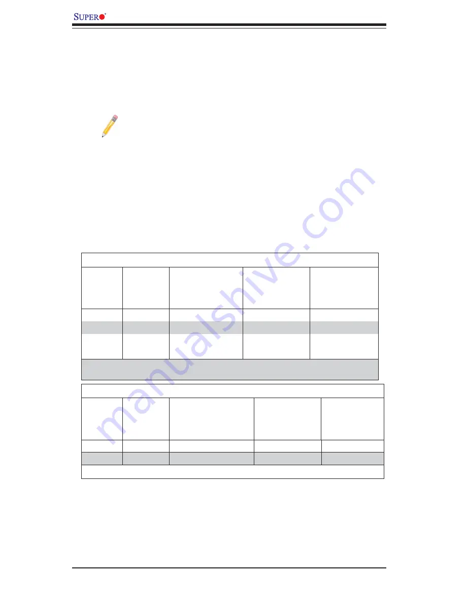
RDIMM Population for the Motherboard with 5500 Processors Installed

DIMM 
Slots per 
Channel

DIMMs 
Populated 
per Channel

DIMM Type (Reg.= 
Registered)

Speeds (in MHz)

Ranks per DIMM 
(any combination; 
SR=Single Rank,
DR=Dual Rank,
QR=Quad Rank)

2

1

Reg. DDR3 ECC

800,1066,1333

SR or DR

2

1

Reg. DDR3 ECC

800,1066 (Note 1)

QR

2

2

Reg. DDR3 ECC

800,1066 (Note 1)

Mixing SR, DR

2

2

Reg. DDR3 ECC

800 (Note 2)

Mixing SR, DR, QR

Note 1:

 1333 RDIMMs will run at 1066 MHz (-BIOS automatic downgrading).

Note 2:

 1333/1066 RDIMMs will run at 800 MHz (-BIOS automatic downgrading).

UDIMM Population for the Motherboard with 5500 Processors Installed

DIMM 
Slots per 
Channel

DIMMs 
Populated 
per Channel

DIMM Type (Unb.= 
Unbuffered)

Speeds (in MHz)

Ranks per DIMM 
(any combination; 
SR=Single Rank,
DR=Dual Rank,
QR=Quad Rank)

2

1

Unb. DDR3 ECC/Non-ECC

800,1066,1333

SR or DR

2

2

Unb. DDR3 ECC/Non-ECC

800,1066 (Note)

Mixing SR, DR

Note:

 1333 UDIMMs will run at 800 MHz (-BIOS automatic downgrading)

Summary of Contents for SUPERO X8DTG-QF

Page 1: ...X8DTG QF USER S MANUAL Revision 1 0a...

Page 2: ...F SUCH DAMAGES IN PARTICULAR SUPERMICRO SHALL NOT HAVE LIABILITY FOR ANY HARDWARE SOFTWARE OR DATA STORED OR USED WITH THE PRODUCT INCLUDING THE COSTS OF REPAIRING REPLACING INTEGRATING INSTALLING OR...

Page 3: ...d processors This product is intended to be installed and serviced by professional technicians Manual Organization Chapter 1 describes the features specifications and performance of the mother board a...

Page 4: ...ual Warning Important information given to ensure proper system installation or to prevent damage to the components Note Additional Information given to differentiate various models or to ensure corre...

Page 5: ...Micro Computer B V Het Sterrenbeeld 28 5215 ML s Hertogenbosch The Netherlands Tel 31 0 73 6400390 Fax 31 0 73 6416525 Email sales supermicro nl General Information support supermicro nl Technical Su...

Page 6: ...nstalling a CPU Heatsink 2 5 2 4 Memory Installation 2 7 2 5 Control Panel Connectors IO Ports 2 12 Back Panel Connectors IO Ports 2 12 Back Panel Connector Pin Definitions 2 13 Universal Serial Bus U...

Page 7: ...LEDs 2 34 Onboard Power LED 2 35 BMC Activity LED 2 35 2 9 Serial ATA Connections 2 36 Serial ATA Ports 2 36 Chapter 3 Troubleshooting 3 1 Troubleshooting Procedures 3 1 Before Power On 3 1 No Power...

Page 8: ...2 Boot Sector Recovery from an IDE CD ROM 4 28 4 7 3 Boot Sector Recovery from a Serial Port Serial Flash 4 28 Appendix A BIOS Error Beep Codes A 1 BIOS Error Beep Codes A 1 Appendix B Installing the...

Page 9: ...detail to provide you with the highest standards in quality and performance Check that the following items have all been included with your motherboard If anything listed here is damaged or missing co...

Page 10: ...pictures shown in this manual were based on the latest PCB Revision available at the time of publishing of the manual The motherboard you ve received may or may not look exactly the same as the graphi...

Page 11: ...UDIO FP CD IN Slot10 PCI E 2 0 x16 Slot8 PCI E 2 0 x16 Slot6 PCI E 2 0 x16 Slot5 PCI 33MHz Slot3 PCI 33MHz Slot2 PCI E 2 0 x4 in x16 Slot FAN10 FAN9 FAN7 CPU1 FAN8 CPU2 IPMI_LAN ALWAYS POPULATE DIMM A...

Page 12: ...3 PCI 33MHz Slot2 PCI E 2 0 x4 in x16 Slot FAN10 FAN9 FAN7 CPU1 FAN8 CPU2 IPMI_LAN ALWAYS POPULATE DIMM A FIRST USB2 3 4 5 P2 DIMM3A P2 DIMM2A P2 DIMM2B P2 DIMM1B P2 DIMM3B P2 DIMM1A P1 DIMM3B P1 DIMM...

Page 13: ...COM2 COM1 COM2 Serial Connections FAN 1 10 System CPU Fan Headers Fans 7 8 CPU Fans I SATA0 5 Intel South Bridge SATA Ports 0 5 JD1 PWR LED Pins 1 3 Speaker Pins 4 7 JF1 Front Panel Connector JL1 Cha...

Page 14: ...0R South Bridge Expansion Slots Four PCI E Gen 2 0 x16 slots Slot 4 Slot 6 Slot 8 Slot 10 One PCI E Gen 1 0 x4 in x16 slot Slot 1 One PCI E Gen 2 0 x4 in x16 slot Slot 2 One PCI E Gen 2 0 x4 in x8 slo...

Page 15: ...ent Controller supports IPMI 2 0 with KVM support Dual Intel 82574 Dual LAN Gigabit Ethernet Controllers support dual Giga bit LAN ports Onboard PHY Chip supports IPMI dedicated LAN Two serial port co...

Page 16: ...I 33MHZ SIO LPC BUS 5 6 REAR 2 Internal 2 Type A 6 FRONT LAN1 LAN2 SPI WPCM450 BIOS Ports 1 2 HD ALC888 AUDIO CONN COM1 VGA1 CSI1 CSI1 CSI0 CSI0 PCI E x16 PCI E x16 6 7 8 9 TPM Keyboard LAN Ports 3 4...

Page 17: ...s for transmission and receiving in addition to a differential forwarded clock A full width QPI link pair provides 84 signals Each processor supports two QuickPath links one going to the other process...

Page 18: ...vity of the voltage monitor Fan Status Monitor with Firmware Control The PC health monitor can check the RPM status of the cooling fans The onboard CPU and chassis fans are controlled by Thermal Manag...

Page 19: ...low Blinking LED for Suspend State Indicator When the CPU goes into a suspend state the chassis power LED will start blinking to indicate that the CPU is in suspend mode When the user presses any key...

Page 20: ...CI interface to com municate with the graphics core It supports USB 2 0 and 1 1 for remote keyboard mouse virtual media emulation It also provides LPC interface to control Super IO functions The WPCM4...

Page 21: ...not touch its components peripheral chips memory modules or gold contacts When handling chips or modules avoid touching their pins Put the motherboard and peripherals back into their antistatic bags...

Page 22: ...s 1 Locate the mounting holes on the 2 motherboard Refer to the layout above for mounting hole locations Locate the matching mounting holes 3 on the chassis Align the mounting holes on the motherboard...

Page 23: ...eatsink fans When purchasing a motherboard without the 5500 5600 Series processor pre 3 installed make sure that the CPU socket plastic cap is in place and none of the CPU socket pins are bent otherwi...

Page 24: ...f the socket or its pins to avoid damaging the CPU or the socket With the CPU inside the socket in 7 spect the four corners of the CPU to make sure that the CPU is properly installed Once the CPU is s...

Page 25: ...e applied Screw 1 Screw 2 Install Screw 1 Place the heatsink on top of the 2 CPU so that the four mounting holes are aligned with those on the retention mechanism 3 Install two diagonal screws ie the...

Page 26: ...3 remove the heatsink screws from the motherboard in the se quence as show in the picture on the right Hold the heatsink as shown 4 in the picture on the right and gently wriggle the heatsink to loose...

Page 27: ...ttom of the module to prevent inserting the DIMM module incor rectly Gently press down on the DIMM module until it snaps into place in the slot 3 Repeat for all modules Memory Population for Optimal P...

Page 28: ...d DIMM Slots per Channel DIMMs Populated per Channel DIMM Type Reg Registered Speeds in MHz Ranks per DIMM any combination SR Single Rank DR Dual Rank QR Quad Rank 2 1 Reg DDR3 ECC 800 1066 1333 SR or...

Page 29: ...Unbuffered Speeds in MHz Ranks per DIMM any combination SR Single Rank DR Dual Rank QR Quad Rank 2 1 Unb DDR3 ECC Non ECC 800 1066 1333 SR or DR 2 2 Unb DDR3 ECC Non ECC 800 1066 1333 Mixing SR DR Not...

Page 30: ...more than 4 GB of memory Note 2 Due to memory allocation to system devices the amount of mem ory that remains available for operational use will be reduced when 4 GB of RAM is used The reduction in me...

Page 31: ...ntion to the alignment notch at the bottom Installing and Removing DIMMs To Remove Use your thumbs to gently push the release tabs near both ends of the module This should release it from the slot Not...

Page 32: ...colors and locations of the various I O ports Back Panel Connectors IO Ports 1 2 3 4 5 6 7 8 9 16 10 11 12 13 14 15 Back Panel Connectors Keyboard Purple 1 PS 2 Mouse Green 2 COM Port 1 Turquoise 3 VG...

Page 33: ...luded See the tables on the right for pin definitions Back Panel USB 0 1 2 3 4 5 Pin Definitions Pin Definition Pin Definition 1 5V 5 5V 2 USB_PN1 6 USB_PN0 3 USB_PP1 7 USB_PP0 4 Ground 8 Ground Front...

Page 34: ...J45 type cables Note Please refer to the LED In dicator Section for LAN LED information LAN Ports Pin Definition Pin Definition Pin Definitions 1 P2V5SB 10 SGND 2 TD0 11 Act LED 3 TD0 12 P3V3SB 4 TD1...

Page 35: ...eader 3 VGA Port X8DTG QF Rev 2 0 1 2 3 Serial Ports Two COM connections COM1 COM2 are located on the motherboard COM1 is located on the Backplane IO panel COM2 is header located next to PCI E Slot 1...

Page 36: ...th your motherboard to use this feature CD 10 pin Audio Headers A 4 pin CD header CD1 and a 10 pin Front Panel Audio header J138 are also located on the motherboard These headers allow you to use the...

Page 37: ...rs are designed specifically for use with Supermicro server chassis See the figure below for the descriptions of the various control panel buttons and LED indicators Refer to the following section for...

Page 38: ...Pin Definitions A B Power LED The Power LED connection is located on pins 15 and 16 of JF1 Refer to the table on the right for pin definitions NMI Button The non maskable interrupt button header is l...

Page 39: ...ork Interface Controller LED connections for GLAN Port 1 are located on pins 11 and 12 and for GLAN Port 2 are on pins 9 and 10 of JF1 Attach NIC LED cables to dis play LAN port connections and activi...

Page 40: ...ions PWR Fail LED Pin Definitions JF1 Pin Definition 5 3 3V 6 PWR Fail LED A OH Fan Fail PWR Fail LED B PWR Supply Fail X8DTG QF Rev 2 0 B Overheat OH Fan Fail LED Connect an LED cable to the OH Fan F...

Page 41: ...ion as a suspend button with a setting in the BIOS see Chapter 4 Press the button for at least 4 seconds to turn off the power supply when in the suspend mode Refer to the table on the right for pin d...

Page 42: ...1 CPU2 CPU1 FAN6 ICH 10R Intel JTPM1 TPM 2 6 Connecting Cables Power Connectors A 24 pin main power supply connector JPW1 and two 8 pin CPU PWR connectors JPW2 JPW3 on the motherboard These power conn...

Page 43: ...OS JF1 Intel 5520 IOH 36D Intel 5520 IOH 36D WPCM450 BMC CTRL LAN CTRL 82574 LAN CTRL 82574 PHY Slot11 PCI E 2 0 x4 in x8 Slot ALC888 Audio CTRL CPU VRM IPMI Firmware Memory for IPMI Rev 2 0 USB8 9 US...

Page 44: ...11 PCI E 2 0 x4 in x8 Slot ALC888 Audio CTRL CPU VRM IPMI Firmware Memory for IPMI Rev 2 0 USB8 9 USB6 USB7 JOH1 JL1 JPUSB2 JPUSB1 CPU2 CPU1 FAN6 ICH 10R Intel JTPM1 TPM B A A PWR LED Speaker Header B...

Page 45: ...6D WPCM450 BMC CTRL LAN CTRL 82574 LAN CTRL 82574 PHY Slot11 PCI E 2 0 x4 in x8 Slot ALC888 Audio CTRL CPU VRM IPMI Firmware Memory for IPMI Rev 2 0 USB8 9 USB6 USB7 JOH1 JL1 JPUSB2 JPUSB1 CPU2 CPU1 F...

Page 46: ...E 2 0 x16 LAN2 VGA COM1 KB MOUSE PWR I2C USB0 1 LAN1 COM2 X8DTG QF JPW1 JPW2 BIOS JF1 Intel 5520 IOH 36D Intel 5520 IOH 36D WPCM450 BMC CTRL LAN CTRL 82574 LAN CTRL 82574 PHY Slot11 PCI E 2 0 x4 in x8...

Page 47: ...l 5520 IOH 36D Intel 5520 IOH 36D WPCM450 BMC CTRL LAN CTRL 82574 LAN CTRL 82574 PHY Slot11 PCI E 2 0 x4 in x8 Slot ALC888 Audio CTRL CPU VRM IPMI Firmware Memory for IPMI Rev 2 0 USB8 9 USB6 USB7 JOH...

Page 48: ...2 JP6 1 JP3 1 JI2C1 JI2C2 JL2 JPL2 JWD JPG1 JPAC JPL1 JPW3 JBT1 JSMB1 J138 D33 DP1 CD1 JAUDIO1 SP1 FAN2 FAN1 FAN5 FAN4 FAN3 JD1 AUDIO FP CD IN Slot10 PCI E 2 0 x16 Slot8 PCI E 2 0 x16 Slot6 PCI E 2 0...

Page 49: ...SATA3 I SATA4 I SATA5 JWOL Battery JPI2C J18 T SGPIO1 T SGPIO2 JP6 1 JP3 1 JI2C1 JI2C2 JL2 JPL2 JWD JPG1 JPAC JPL1 JPW3 JBT1 JSMB1 J138 D33 DP1 CD1 JAUDIO1 SP1 FAN2 FAN1 FAN5 FAN4 FAN3 JD1 AUDIO FP C...

Page 50: ...MI Rev 2 0 USB8 9 USB6 USB7 JOH1 JL1 JPUSB2 JPUSB1 CPU2 CPU1 FAN6 ICH 10R Intel JTPM1 TPM A CMOS Clear B WD CMOS Clear JBT1 is used to clear CMOS Instead of pins this jumper consists of contact pads t...

Page 51: ...D WPCM450 BMC CTRL LAN CTRL 82574 LAN CTRL 82574 PHY Slot11 PCI E 2 0 x4 in x8 Slot ALC888 Audio CTRL CPU VRM IPMI Firmware Memory for IPMI Rev 2 0 USB8 9 USB6 USB7 JOH1 JL1 JPUSB2 JPUSB1 CPU2 CPU1 FA...

Page 52: ...PMI Firmware Memory for IPMI Rev 2 0 USB8 9 USB6 USB7 JOH1 JL1 JPUSB2 JPUSB1 CPU2 CPU1 FAN6 ICH 10R Intel JTPM1 TPM A BP USB Enable B VGA Enable B A FP USB Wake up Enable JPUSB2 Jumper Settings Pin De...

Page 53: ...1 DIMM3A P1 DIMM2A P1 DIMM1B P1 DIMM1A ALWAYS POPULATE DIMM A FIRST FP CTRL Slot1 PCI E x4 in x16 Slot Slot4 PCI E 2 0 x16 LAN2 VGA COM1 KB MOUSE PWR I2C USB0 1 LAN1 COM2 X8DTG QF JPW1 JPW2 BIOS JF1 I...

Page 54: ...BMC CTRL LAN CTRL 82574 LAN CTRL 82574 PHY Slot11 PCI E 2 0 x4 in x8 Slot ALC888 Audio CTRL CPU VRM IPMI Firmware Memory for IPMI Rev 2 0 USB8 9 USB6 USB7 JOH1 JL1 JPUSB2 JPUSB1 CPU2 CPU1 FAN6 ICH 10...

Page 55: ...S JF1 Intel 5520 IOH 36D Intel 5520 IOH 36D WPCM450 BMC CTRL LAN CTRL 82574 LAN CTRL 82574 PHY Slot11 PCI E 2 0 x4 in x8 Slot ALC888 Audio CTRL CPU VRM IPMI Firmware Memory for IPMI Rev 2 0 USB8 9 USB...

Page 56: ...I E 2 0 x16 LAN2 VGA COM1 KB MOUSE PWR I2C USB0 1 LAN1 COM2 X8DTG QF JPW1 JPW2 BIOS JF1 Intel 5520 IOH 36D Intel 5520 IOH 36D WPCM450 BMC CTRL LAN CTRL 82574 LAN CTRL 82574 PHY Slot11 PCI E 2 0 x4 in...

Page 57: ...board and 1 chassis Disconnect all ribbon wire cables from the motherboard including those for 2 the keyboard and mouse Remove all add on cards 3 Install CPU 1 first making sure it is fully seated and...

Page 58: ...ory Errors When a No_Memory_Beep_Code is issued by the system check the following Make sure that the DIMM modules are properly and fully installed 1 Check if different speeds of DIMMs have been instal...

Page 59: ...support bios If you still cannot resolve the problem include the following information when 3 contacting Supermicro for technical support Motherboard model and PCB revision number BIOS release date v...

Page 60: ...annot be removed Send your motherboard back to our RMA Department at Supermicro for repair Question What s on the CD that came with my motherboard Answer The supplied compact disc has quite a few driv...

Page 61: ...key legend Above the key legend is an area reserved for a text message When an option is selected in the left frame it is highlighted in white Often a text message will accompany it The AMI BIOS Setu...

Page 62: ...em while the BIOS is updating This is to avoid possible boot failure 4 2 Main Setup When you first enter the AMI BIOS Setup Utility you will enter the Main setup screen You can always return to the Ma...

Page 63: ...cessor used in your system CPU Type This item displays the type of CPU used in the motherboard Speed This item displays the speed of the CPU detected by the BIOS Physical Count This item displays the...

Page 64: ...display the POST messages Select Enabled to display the OEM logo instead of the normal POST messages The op tions are Enabled and Disabled AddOn ROM Display Mode This sets the display mode for the Op...

Page 65: ...e Enabled and Disabled Power Button Function If set to Instant_Off the system will power off immediately as soon as the user hits the power button If set to 4_Second_Override the system will power off...

Page 66: ...ns are Modern Ordering and Legacy Ordering Intel Virtualization Technology Available when supported by the CPU Select Enabled to use the feature of Virtualization Technology to allow one platform to r...

Page 67: ...t State C1E significantly reduces the CPU s power consumption by reducing the CPU s clock cycle and voltage during a Halt State The options are Disabled and Enabled Intel C State Tech If enabled C Sta...

Page 68: ...detected to run at the frequency as specified The available options are Auto Force DDR 800 Force DDR 1066 Force DDR 1333 and Force SPD Memory Mode The options are Independent Channel Mirroring and Loc...

Page 69: ...this feature set to Enabled it will enhance overall system performance by providing direct cache access for data transferring The options are Enabled and Disabled DCA Prefetch Delay A DCA Prefetch is...

Page 70: ...led and Auto USB 2 0 Controller Select Enabled to activate USB 2 0 Controller The options are Enabled and Dis abled Note If the item USB Functions is enabled USB 2 0 Controller will always be enabled...

Page 71: ...de Base will appear When the option AHCI is selected the item ICH AHCI Codebase will be available ICH RAID Code Base Available when the option RAID is selected Select Intel to enable Intel s SATA RAID...

Page 72: ...ts 48 bit LBA mode The options are Disabled and Auto Block Multi Sector Transfer Block Mode boosts the IDE drive performance by increasing the amount of data transferred Only 512 bytes of data can be...

Page 73: ...f 13 3 MB s Select MWDMA2 to allow the BIOS to use Multi Word DMA mode 2 It has a data transfer rate of 16 6 MB s Select UDMA0 to allow the BIOS to use Ultra DMA mode 0 It has a data transfer rate of...

Page 74: ...PCI latency to 64 PCI clock cycles The options are 32 64 96 128 160 192 224 and 248 PCI IDE BusMaster When enabled the BIOS uses PCI bus mastering for reading writing to IDE drives The options are Di...

Page 75: ...comes unavailable Select 3F8 IRQ4 to allow the serial port to use 3F8 as its I O port address and IRQ 4 for the interrupt address The options for Serial Port1 are Disabled 3F8 IRQ4 3E8 IRQ4 2E8 IRQ3 a...

Page 76: ...nal type for Console Redi rection The options are ANSI VT100 and VT UTF8 VT UTF8 Combo Key Support Select Enabled to enable VT UTF8 Combination Key support for ANSI VT100 terminals The options are Ena...

Page 77: ...pt is each CPU is embedded by unique temperature information that the motherboard can read This Temperature Threshold or Tem perature Tolerance has been assigned at the factory and is the baseline on...

Page 78: ...Celsius and Fahrenheit as detected by the BIOS Fan1 Fan 10 Reading This feature displays the fan speed readings from Fan1 through Fan8 Fan1 is CPU1 Fan and Fan2 is CPU2 Fan Fan Speed Control Modes Thi...

Page 79: ...O S Enable ACPI support if it is supported by the OS to control ACPI through the Operat ing System Otherwise disable this feature The options are Yes and No Suspend Mode Available ACPI Aware O S Yes...

Page 80: ...PM device The options are Don t Change Set and Clear TPM Owner This feature installs or clears TPM ownership The options are Don t Change En able Install Disable Install and Clear Execute TPM Command...

Page 81: ...t select an Entry Number and pressing Enter to display the information as shown in the screen SEL Entry Number SEL Record ID SEL Record Type Event Timestamp Generator ID Event Message Format Ver Event...

Page 82: ...ailable for configuration IP Address The BIOS will automatically enter the IP address of this machine however it may be over ridden This should be in decimal and in dotted quad form i e 192 168 10 253...

Page 83: ...re Yes and No 4 4 Security Settings The AMI BIOS provides a Supervisor and a User password If you use both pass words the Supervisor password must be set first Supervisor Password This item indicates...

Page 84: ...ser Password Select this feature and press Enter to enter a new User Password Clear User Password Available only if User Password has been set This item allows you to clear a user password after it ha...

Page 85: ...t Device 2nd Boot Device 3rd Boot Device Removable Drives Use this feature to specify the boot sequence from available Removable Drives The settings are 1st boot device 2nd boot device and Disabled 1s...

Page 86: ...tion and reboot the computer Select Discard Changes and Exit from the Exit menu and press Enter Discard Changes Select this option and press Enter to discard all the changes and return to the AMI BIOS...

Page 87: ...e the bootup process Notes BIOS Recovery described below is used when the main BIOS block crashes However when the BIOS Boot sector crashes you will need to send the motherboard back to Supermicro for...

Page 88: ...h for Boot Sector Recovery you will need to meet the following requirements The Target system the system that needs BIOS updates must have a serial port and Serial Flash support embedded in the BIOS i...

Page 89: ...shing is starting and the new BIOS file is being uploaded 7 To use Hyper Terminal to transfer the XModem protocol by using the Send File dialog under the Transfer menu follow the instructions below to...

Page 90: ...al communications program that supports VT 100 and XModem protocols including protocols designed for GNU LINUX BSD operating systems such as minicom It is recommended that the terminal program be conf...

Page 91: ...allow the system to continue the boot up procedure If a fatal error occurs you should consult with your system manufacturer for possible repairs A 1 BIOS Error Beep Codes BIOS Error Beep Codes Beep Co...

Page 92: ...A 2 X8DTG QF User s Manual Notes...

Page 93: ...start booting up from CD Press the F6 key when the message Press F6 if you need to install a 2 third party SCSI or RAID driver displays When the Windows XP Windows 2003 Setup screen appears press S to...

Page 94: ...nstallation The Windows OS Setup screen will display 2 From the Windows OS Setup screen press the Enter key The Windows 3 OS Setup will automatically load all device files and then continue with the W...

Page 95: ...ew the entire contents of the CD 2 When making a storage driver diskette by booting into a Driver CD please set the SATA Configuration to Compatible Mode and configure SATA as IDE in the BIOS Setup Af...

Page 96: ...displays crucial system information such as CPU temperature system voltages and fan status See the Figure below for a display of the Supero Doctor III interface Note 1 The default user name and passw...

Page 97: ...te Control Note SD III Software Revision 1 0 can be downloaded from our Web site at ftp ftp supermicro com utility Supero_Doctor_III You can also download SDIII User s Guide at http www supermicro com...

Page 98: ...C 4 X8DTG QF User s Manual Notes...

Page 99: ...expected to result in significant injury or loss of life or catastrophic property damage Accordingly Supermicro disclaims any and all liability and should buyer use or sell such products for use in su...

Reviews: