


M14T Mobile Rack User's Guide
2-2
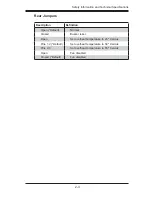
Fan Header
Pin Defi nitions (JP22)
Pin# Defi nition
1
Ground
2
+12V
3
Tachometer
Rear Side Connectors
J P 1 0 : 4 - p i n p o w e r c o n n e c t o r
The 4-pin power connector designated JP10, is
located on the rear side of the SASM14V back-
plane. This power connector must be connected
to your power supply in order to provide adequate
power to the backplane. See the table on the right
for pin defi nitions.
JP11: SAS-In Connector
JP22: 3-pin Fan Header. The 3-pin fan header
designated JP22, located on the rear side of the
SASM14V backplane. Connect a cable to the fan
header to provide cooling to the backplane. See
the table on the right for pin defi nitions.
JP26: ACT-In Header
The 4-pin Act-In header designated JP26, is lo-
cated on the rear side of the SASM14V backplane.
It indicates the activity status of the SAS/SATA slots
that are on the front of the backplane. See the table
on the right for pin defi nitions.
+12V
+12V
GND
GND
+5V
+5V
GND
GND
11
11
11
JP42
JP22
Fan
JP10
4-Pin PWR
JP25
SAS In
ACT In
Figure 2-2: Rear Connectors and Jumpers
JP18
J11
JP26
Act-In Header
Pin Defi nitions (JP26)
Pin# Defi nition
Open
Act-In#0-#3 (Default)
1
Act-In#0
2
Act-In#1
3
Act-In#2
4
Act-In#3
4-pin Power Connector
Pin Defi nitions
Pin# Defi nition
1
+12V
2
Ground
3
Ground
4
+5V
2-2 SASM14V Rear Connectors and Jumpers


