


1-1
Chapter 1: Introduction
Chapter 1
Introduction
1-1 Overview
Supermicro's SC827HD chassis is designed to optimize performance per Watt and
per dollar with two independent hot-pluggable dual processor computing nodes,
efficiently organized into a 2U form factor. Each node provides six 3.5" hard drives
for RAID 5 data protection, and is contained in a convenient module to facilitate
easy system upgrades, installation and maintenance. The SC827HD chassis is
equipped one of two power supplies.
•
1400 Watt high-efficiency 1 + 1 80+ Gold level, redundant
•
1620 Watt high-efficiency 94+ Platinum level, redundant
It includes a power-efficient server board and optimized cooling subsystems. The
2U Twin is the best choice for HPC, datacenter and cost-effective blade-type ap-
plications.
Note:
A complete list of safety warnings is provided on the web at, http://www.
supermicro.com/about/policies/safety_information.cfm.
1-2 Shipping List
Part Numbers
Visit the following link for the latest shiping lists and part numbers for your particular
chassis model: http://www.supermicro.com/products/chassis/2U/827/SC827HD-
Rxxxx.cfm
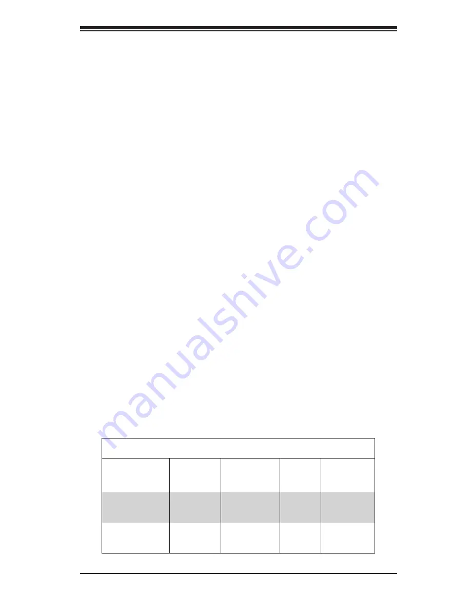
SC827HD Chassis
Model
MB Node
Hot-Swap
Feature
HDD
I/O
Slots
Power
Supply
SC827HD-
R1400B
Yes
12x SAS/SATA
2x FH
1x LP
per node
1400W Re-
dundant
SC827HD-
R1620B
Yes
12x SAS/SATA
2x FH
1x LP
per node
1620W Re-
dundant
LP = Low profile
FH = Full height
Summary of Contents for SC827HD-R1400B
Page 1: ...SC827HD Chassis Series USER S MANUAL 1 0 SUPER SC827HD R1400B SC827HD R1620B...
Page 12: ...SC827HD Chassis Manual 1 4 Notes...
Page 32: ...2 20 SC827HD Chasssis Manual Notes...
Page 38: ...SC827HD Chassis Manual 4 4 Notes...
Page 68: ...SC827HD Chassis Manual 6 10 Notes...
Page 70: ...SC827HD Chassis Manual A 2 Notes...
Page 72: ...SC827HD Chassis Manual B 2 Notes...
Page 81: ...C 9 Appendix C Backplane Notes...


