background image

1-6

SC742 Chassis


User’s Guide

1-2 Technical Specifi cations

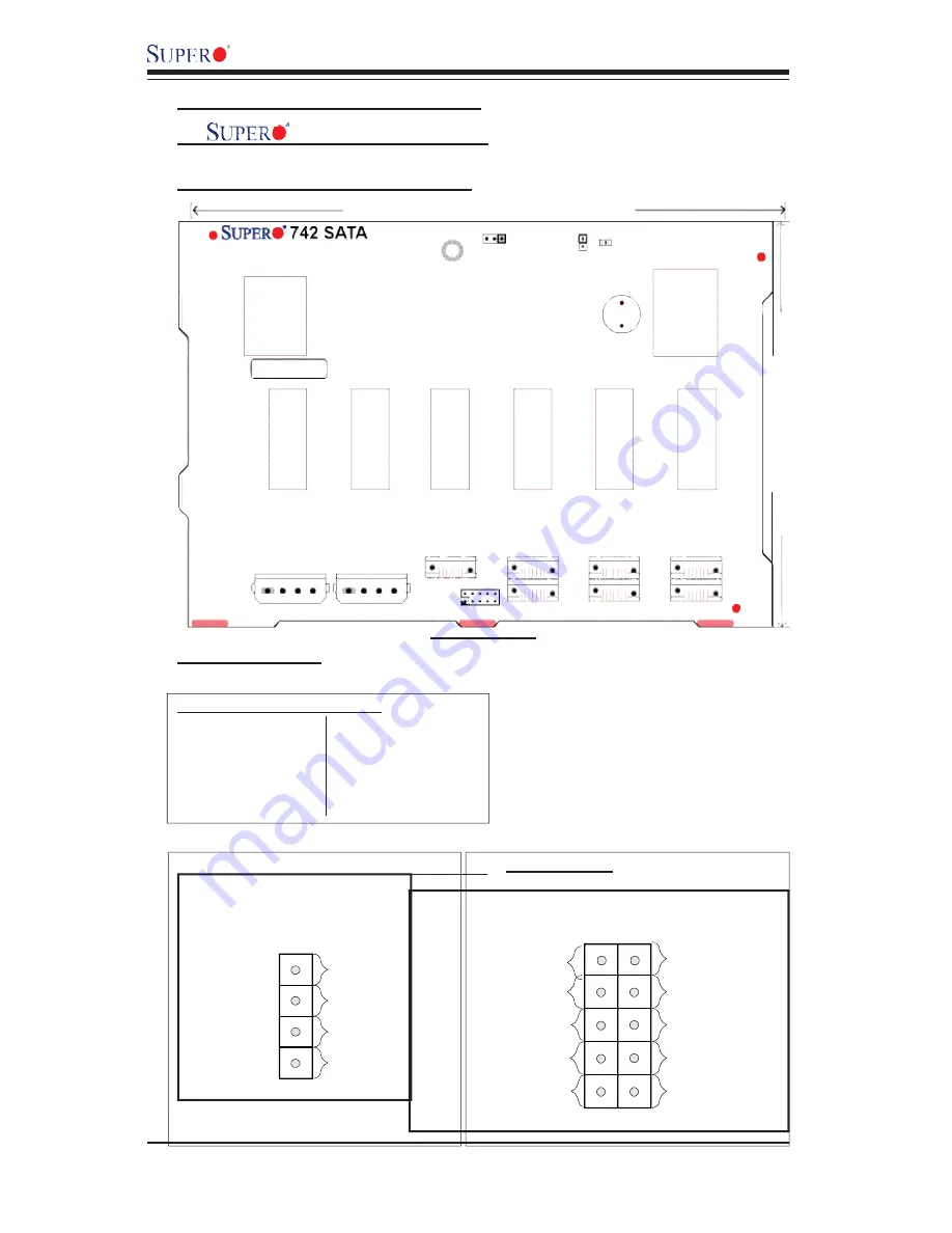
A.             742 SATA Back Panel 

A-1 Connector/Jumper Locations

Front View

A-2  Connectors

D3: Overheat LED Indicator

J5: SATA #0 


J6: SATA#1

J7: SATA #2 


J8: SATA#3

J10: SATA #4 


J12: SATA#5

J14: SATA #6 


SATA#0 Act In

SATA#5 Act In

1

x

SATA#1 Act In

2

SATA#4 Act In

9

10

SATA#6 Act In

SATA#2 Act In

SATA#3 Act In

x

Act In (JP26) Pin Definitions

x

JP10/ JP13:  4-Pin PWR Connectors   

JP26:  ACT In   

199.70MM

135.00MM

JP25

1

1

JP18

D3

J5

J6

J7

J8

J10

J12

J14

JP26

JP13

JP10

4 - P i n 

PWR

4 - P i n 

PWR

+12V

1

Ground

4

Ground

+5V

4-Pin PWR Connectors

Pin Definitions

2

3

Summary of Contents for SC742i

Page 1: ...1 0b SC742 CHASSIS USER S GUIDE 742S 742i...

Page 2: ...THE USE OR INABILITY TO USE THIS PRODUCT OR DOCUMENTATION EVEN IF ADVISED OF THE POSSIBILITY OF SUCH DAMAGES IN PARTICULAR THE VENDOR SHALL NOT HAVE LIABILITY FOR ANY HARDWARE SOFTWARE OR DATA STORED...

Page 3: ...ical Speci cations 1 4 1 1 Safety Information 1 4 1 2 Technical Speci cations 1 6 A 742 SATA Back Panel 1 6 B SCA742 E2 SCSI Dual Channel Back Panel w GEM318 1 8 C SCA 742 SCSI Single Channel Back Pan...

Page 4: ...gold contacts When handling chips or modules avoid touching their pins Put the motherboard and peripherals back into their antistatic bags when not in use For grounding purposes make sure your compute...

Page 5: ...asteners for later use If necessary label these screws or fasteners for easy identi cation 3 Follow the instruction given in Chapter 2 to remove the chassis covers Reinstalling the chassis covers To m...

Page 6: ...A 2 J8 SATA 3 J10 SATA 4 J12 SATA 5 J14 SATA 6 SATA 0 Act In SATA 5 Act In 1 x SATA 1 Act In 2 SATA 4 Act In 9 10 SATA 6 Act In SATA 2 Act In SATA 3 Act In x Act In JP26 Pin Definitions x JP10 JP13 4...

Page 7: ...on and Technical Speci cations A 3 Jumpers JP18 Buzzer Reset Rear View Not drawn to scale A 4 Connector LED Indicator Locations Rear Side A 5 Activity LED Indicators D22 D21 D18 D15 D14 D13 D12 J1 J2...

Page 8: ...t Drawn to Scale B 1 Connector Jumper Locations B 2 Connectors JP10 JP15 4 Pin PWR Connectors 12V 1 Ground 4 Ground 5V 4 Pin PWR Connectors Pin Definitions 2 3 B 3 Jumpers JP18 Buzzer Reset JP23 JP20...

Page 9: ...r LED Indicator Locations Rear Rear View Not drawn to scale D24 D25 D23 D20 D22 D15 D17 D14 D13 D16 D6 D12 D5 Ch A ID 0 Ch A ID 1 Ch A ID 2 Ch B ID 0 Ch B ID 1 Ch B ID 2 Ch B ID 3 D21 B 5 LED Indicato...

Page 10: ...e Channel Back Panel w GEM359 Front View Not Drawn to Scale C 1 Connector Jumper Locations C 2 Connectors JP10 JP26 4 Pin PWR Connectors 12V 1 Ground 4 Ground 5V 4 Pin PWR Connectors Pin Definitions 2...

Page 11: ...tions C 4 Connector LED Indicator Locations Rear Rear View Not drawn to scale D22 D19 D18 D20 D17 D15 D16 D14 D13 D7 D6 D12 D5 ID 0 ID 1 ID 2 ID 3 ID 4 ID 5 ID 6 D21 C 5 LED Indicators Rear SCSI Drive...

Page 12: ...CD is in 8 Choose Qlogic folder and click on Open 9 System will automatically detect GEM318 GEM359 and install the drive from this point on or 1 Right click the My Computer icon on your desktop and c...

Page 13: ...fety Information and Technical Speci cations Important The chassis handles are for sliding the chassis in and out of the racks only Do not carry the chassis by the handles to avoid system damage or bo...

Reviews: