SC503 Chassis Manual
4-6
A
1
B
C
D
E
F
G
H
I
J
K
L
M
2
3
4
5
6
7
8
9
10
DESIGN / ³]-p :
MODEL NO./ ¾÷«¬ :
SIZE/¹Ï®Ø
APPROVED / ¼f®Ö :
DRAWN / ø¹Ï :
MATERIAL / §÷½è :
UNIT / ³æ¦ì :
FINISH / ªí-±³B¸Ì :
DATE / ¤é´Á:
DATE / ¤é´Á:
DATE / ¤é´Á:
TITLE / «~¦W :
PART NO. / ®Æ¸¹ :
Ablecom Technology Inc.
A
BLEC
DWG NO. / ¹Ï¸¹ :
¤j˚T¬ì§ÞªÑ¥÷¦³--¤½¥q
THE 3RD PROJECTION
²Ä¤T¨¤ªk
M
R E V I S I O N S / -×-q
REV
ª©¥»
DESCRIPTION
±Ô-z
LOCATION
¦ì¸m
DRAWN
-קïªÌ
DATE
¤é´Á
SC503_SYSTEM_ASSY
A0
*
SCALE / ¤ñ¨Ò :
1:1
SHEET
1 OF
1
SC503
*
SHO
03-Dec-07
See Note.
SHO
03-Dec-07
MM
*
REV.
ª©¥»
1
RANGE
½d³ò
TOLERANCE
¤½®t
X.xx
± 0.10
X.x
± 0.25
X
± 1.00
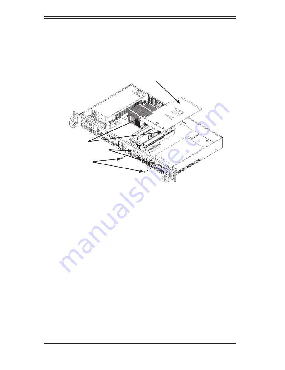
Add-on Card/Expansion Slot Setup
SC503 chassis includes an I/O slot for the optional add-on card. A full-height, half-
length PCI add-on card is supported. A riser card is required in order to adapt the
add-on card to the 1U chassis. For additional information on add-on cards and
risers cards, refer to the Supermicro website at www.supermicro.com
Figure 4-5: Installing the Add-on Card
Disconnect the chassis from the power source.
Outside of the chassis, insert the add-on card into the riser card.
Insert the riser card, with the attached add-on card, into the expansion slot.
Carefully align the thru holes of the add-on card bracket with the thru holes in
the front of the chassis.
Using the mounting screws provided with the bracket, insert the screws
through the thru holes in the front of the chassis into the corresponding
threaded holes in the add-on card bracket.
1.
2.
3.
4.
5.
Add-on Card
Threaded Holes
Thru Holes
Mounting Screws
Summary of Contents for SC503 Series
Page 32: ...SC503 Chassis Manual 5 6 Notes ...


