SBA-7142G-T4 Blade Module User’s Manual
4-2
4-1
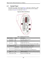
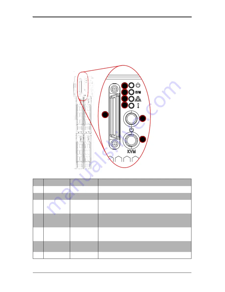
Control Panel
Each blade has a similar control panel (
Figure 4-2
) with power on/off button, a KVM
connector, a KVM button and four LEDs on the top front of the unit. The numbers
mentioned in
Figure 4-2
are described in
Table 4-2
.
Figure 4-2. Blade Control Panel
Table 4-2. Blade Control Panel
Item Function
State
Description
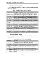
1
Power Button
N/A
Turns blade module on and off
2
KVM Button
N/A
Initiates KVM function
3
Power LED
Green
Indicates power status “On”
Orange
Indicates power status “Off” (with power cables plugged in)
4
KVM/UID LED
Blue
Indicates KVM being utilized on blade unit
Flashing Blue
Indicates UID activated on blade module
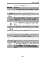
5
Network/IB LED
Flashing Green
Indicates network activity over LAN
Flashing Orange Indicates network activity over InfiniBand module
6
System Fault
LED
Red
Indicates a memory error, overheat, VGA error or any error
that prevents booting
7
KVM Connector N/A
Connector for SUV/KVM cable
1
5
4
3
6
7
2
Summary of Contents for SBA-7142G-T4
Page 1: ...SBA 7142G T4 Blade Module User s Manual Revison 1 0a ...
Page 4: ...SBA 7142G T4 Blade Module User s Manual iv Notes ...
Page 8: ...SBI 7226T T2 Blade Module User s Manual viii Notes ...
Page 10: ...SBI 7226T T2 Blade Module User s Manual x Notes ...
Page 12: ...SBI 7226T T2 Blade Module User s Manual xii Notes ...
Page 18: ...SBA 7142G T4 Blade Module User s Manual 1 6 Notes ...
Page 22: ...SBA 7142G T4 Blade Module User s Manual 2 4 Notes ...
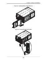
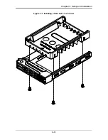
Page 33: ...3 11 Chapter 3 Setup and Installation Figure 3 7 Installing a Hard Drive in a Carrier ...
Page 36: ...SBA 7142G T4 Blade Module User s Manual 3 14 Notes ...
Page 62: ...SBA 7142G T4 Blade Module User s Manual 6 14 Notes ...
Page 74: ...SBA 7142G T4 Blade Module User s Manual A 12 Notes ...


