1-8
H8DA3-2/H8DAi-2 User’s Manual
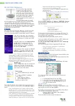
Figure 1-3. nVidia MCP55 Pro/IO-55 Chipset:
System Block Diagram
Note:
This is a general block diagram and may not exactly represent
the features on your serverboard. See the previous pages for the
actual specifi cations of your serverboard.
DIMM 1B
DIMM 2B
nVidia MCP55Pro
AMD Socket F
Processor (CPU2)
16 x 16 HT link (1 GHz)
DIMM 1A
128-bit data + 16-bit ECC
DDR2-667/533
DDR2-667/533
Slot #5: PCI-E x4
Slot #1: PCI-E x8
SATA Ports (6)
IDE: ATA133 (1)
USB Ports (8)
S I/O
BIOS
Floppy
Kybd/
Mouse
Serial Ports
(2)
AMD Socket F
Processor (CPU1)
128-bit data + 16-bit ECC
LPC
DIMM 2A
DIMM 1A
DIMM 1B
DIMM 2A
DIMM 2B
IPMI
nVidia IO-55
Slot #2: PCI
GLAN Ports (2)
Slot #6: PCI-E x16
16 x 16 HT link (1 GHz)
16 x 16 HT link (1 GHz)
PCI-E
SAS Ports (8)
ALC-883 Audio
Parallel
Port
Slot #3: PCI-E x16
Slot #4: PCI-E x4
PCI-E
PCI32
SIMLP
PCI-E
PCI-E
PCI-E