


26
X11SSV-M4F User's Manual
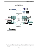
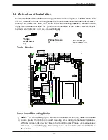
JF1
JPW1
JPW2
JTPM1
JSD1
JSD2
X1
1SSV
-M4F
REV
:1.00
DESIGNED IN USA
FAN2
FAN1
FAN3
JP1
BT1
I-SATA4
I-SATA3
I-SATA2
I-SATA1
JPCIE1 x16
1
J17
JL1
J16
1
JSMB1
JD1
JPG1
JP
AC1
JI2C1
JI2C2
JWD1
JVRM1
JVRM2
JPUSB1
JBR1
JPME1
JGPIO1
I-SGPIO1
1
SRW1
SRW3
JPI2C1
A
LED2
C
LED1
A
SRW2
JBT1
JIPMB1
CPU
NIC3
FF
PWR
FAIL
AUDIO
1-2:ENABLE
2-3:DISABLE
JPAC1:AUDIO
SATA DOM
+POWER
DVI-A
JI2C1/
1-2:ENABLE
JWD1:
JSMB1:SMBus1
2-3:DISABLE
1-2:RST
WATCH DOG
2-3:NMI
M.2
JI2C2:
USB7/8
USB5/6
JPUSB1:
USB0/1 WAKE UP
1-2:ENABLE
2-3:DISABLE
JD1:
4-7:SPEAKER
1-2:NORMAL
JPME1:
1-3:PWR LED
JBR1
1-2:NORMAL
RECOVERY
2-3:ME
RECOVERY
2-3:BIOS
PWR
LED
LAN3/4
LAN1/2
m-PCIE
NIC
HDD
LED
NIC
2
1
DIMMA1
DIMMB1
OH
PWR
ON
RST
KB/MS
USB3/4
USB1/2
USB9
COM1
SRW4
Aspeed
AST2400
Intel
I350-AM2
Intel
CM236
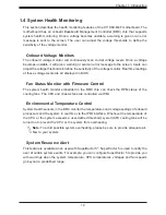
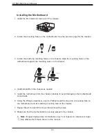
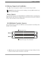
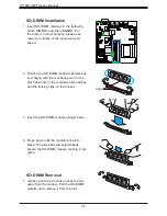
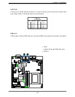
SO-DIMM Installation
1. Insert SO-DIMM modules in the following
order: DIMMA1 and then DIMMB1. For
the system to work properly, please use
memory modules of the same type and
speed.
2. Position the SO-DIMM module's bottom key
so it aligns with the receptive point on the
slot. Take note of the module's side notches
and the locking clips on the socket.
3. Insert the SO-DIMM module straight down.
4. Press down until the module locks into
place. The side clips will automatically
secure the SO-DIMM module, locking it into
place
Align
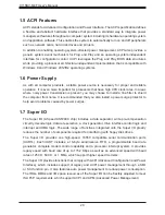
SO-DIMM Removal
1. Gently push the side clips near both ends
away from the module. Pull the SO-DIMM
module up to remove it from the slot.


