SuperWorkstation 5039D-I User's Manual
25
24
Chapter 3: Maintenance and Component Installation
PCI Expansion Card Installation
Three standard size PCI expansion (add-on) cards may be installed in the system.
Installing PCI Expansion Cards
Before installing a PCI add-on card, make sure it is supported by the card slot on the
motherboard.
Begin by removing power from the system as described in section 3.1.
1. Remove the chassis cover to access the inside of the system.
2. Remove the PCI slot shield on the chassis by releasing the locking tab.
3. Insert the expansion (add-on) card into the appropriate PCI slot on the motherboard.
4. Secure the card with the locking tab.
Motherboard Battery
The motherboard uses non-volatile memory to retain system information when system power
is removed. This memory is powered by a lithium battery residing on the motherboard.
Replacing the Battery
Begin by removing power from the system as described in section 3.1.
1. Push aside the small clamp that covers the edge of the battery. When the battery is
released, lift it out of the holder.
2. To insert a new battery, slide one edge under the lip of the holder with the positive (+)
side facing up. Then push the other side down until the clamp snaps over it.
Note:
Handle used batteries carefully. Do not damage the battery in any way; a damaged
battery may release hazardous materials into the environment. Do not discard a used battery
in the garbage or a public landfill. Please comply with the regulations set up by your local
hazardous waste management agency to dispose of your used battery properly.
OR
Figure 3-10. Installing the Onboard Battery
Warning:
There is a danger of explosion if the onboard battery is installed upside down (which
reverses its polarities). This battery must be replaced only with the same or an equivalent type
recommended by the manufacturer (CR2032).
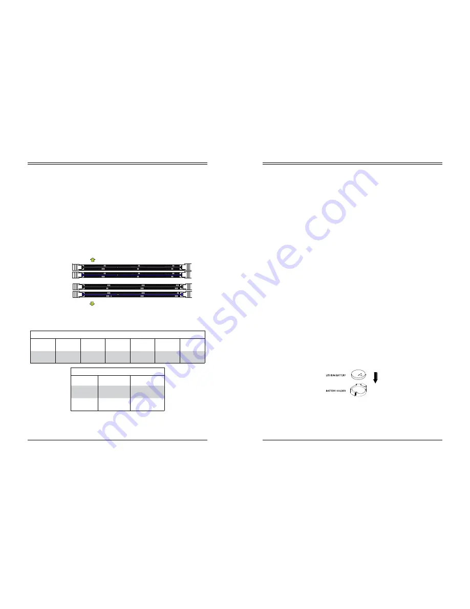
DIMM Module Population Sequence
When installing memory modules, the DIMM slots should be populated in the following order:
DIMMB2, DIMMA2, DIMMB1, DIMMA1.
•
Always use DDR4 DIMM modules of the same type, size and speed.
•
Mixed DIMM speeds can be installed. However, all DIMMs will run at the speed of the
slowest DIMM.
•
The motherboard will support odd-numbered modules (1 or 3 modules installed). However,
for best memory performance, install DIMM modules in pairs to activate memory interleav-
ing.
Figure 3-9. Populating DIMMs
DIMMB2 (Blue Slot)
DIMMA2 (Blue Slot)
Towards the edge of the motherboard
Towards the CPU
DIMMA1
DIMMB1
Memory Module Population
DIMM Slots
per Channel DIMM Type
POR
Speeds
Ranks per
DIMM
Layer
Count
FW Base
Supported
Voltage
2
Unbuffered
DDR4 ECC
2133,1866,
1600, 1333
SR, DR
6
SPS
1.2V
Memory Module Population
Max Memory
Possible
4GB DRAM
Technology
8GB DRAM
Technology
Single Rank
UDIMM
16GB
(4x 4GB DIMMs)
32GB
(4x 8GB DIMMs)
Dual Rank
UDIMMs
32GB
(4x 8GB DIMMs)
64GB
(4x 16GB DIMMs)


