Supermicro SuperStorage SSG-640SP-DE2CR60 User Manual Download Page 71

71

Chapter 4: Motherboard Connections

4.5 LED Indicators

LAN LEDs

Two LAN ports (LAN 1 and LAN 2) are located on the I/O back panel of the motherboard. 
Each Ethernet LAN port has two LEDs. The green LED indicates activity, while the other Link 

LED may be green, amber, or off to indicate the speed of the connection. Refer to the tables 

below for more information.

LAN1/2 Activity LED (Right) 

LED State

Color

Status

Definition

Green

Flashing

Active

LAN1/2 Link LED (Left)

LED States

LED Color

Definition

Green

10Gbps

Yellow/Amber

1Gbps

UID LED

 LED State

LED Color

Definition

Blue: On

Unit Identified

Unit ID LED

A rear UID LED indicator (UID-LED) is located near the UID switch on the I/O back panel. 

This UID indicator provides easy identification of a system unit that may need service.
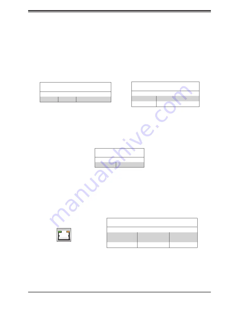
BMC_LAN LEDs

In addition to LAN1 and LAN2, a BMC LAN is also located on the I/O back panel. The 
amber LED on the right indicates activity, while the LED on the left indicates the speed of 
the connection. Refer to the table below for more information. 

BMC LAN

Activity LED

Link LED

LAN 1/LAN 2

IPMI LAN 

(X8ST3-F)

BMC LAN LEDs

LED States

Color/State

Definition

Link (left)

Green: Solid 
Amber: Solid

100 Mbps
1Gbps

Activity (Right)

Amber: Blinking

Active

Summary of Contents for SuperStorage SSG-640SP-DE2CR60

Page 1: ...USER S MANUAL Revision 1 0 SuperStorage Server SSG 640SP DE2CR60...

Page 2: ...Class A device or in residential environment for Class B device This equipment generates uses and can radiate radio frequency energy and if not installed and used in accordance with the manufacturer...

Page 3: ...s and utilities https www supermicro com wdl driver Product safety info http www supermicro com about policies safety_information cfm If you have any questions please contact our support team at suppo...

Page 4: ...tural Diagram 20 1 4 Motherboard Layout 21 Quick Reference Table 22 Chapter 2 Server Installation 2 1 Overview 23 2 2 Unpacking the System 23 2 3 Preparing for Setup 23 Choosing a Setup Location 23 Ra...

Page 5: ...44 Removing the Processor Carrier Assembly from the PHM 45 Removing the Processor from the Processor Carrier Assembly 46 3 5 Memory 47 Memory Support 47 General Memory Population Requirements 47 PMem...

Page 6: ...tion 74 5 2 Driver Installation 76 5 3 SuperDoctor 5 77 5 4 BMC 78 BMC ADMIN User Password 78 Chapter 6 Optional Components 6 1 Optional Parts List 79 6 2 Intel Virtual RAID on CPU VROC 80 Requirement...

Page 7: ...des 91 7 5 Crash Dump Using BMC 92 7 6 UEFI BIOS Recovery 93 Overview 93 Recovering the UEFI BIOS Image 93 Recovering the Main BIOS Block with a USB Device 93 7 7 CMOS Clear 98 7 8 Where to Get Replac...

Page 8: ...et Sterrenbeeld 28 5215 ML s Hertogenbosch The Netherlands Tel 31 0 73 6400390 Fax 31 0 73 6416525 Email sales supermicro nl General Information support supermicro nl Technical Support rma supermicro...

Page 9: ...RDIMM DDR4 288 pin ECC memory with speeds of 3200 2933 2666 MHz in 16 memory slots and up to 4TB of Intel Optane PMem 200 Series with speeds of up to 3200 MHz Drive Support 60 3 5 2 5 hot swap SAS3 d...

Page 10: ...Panels Drawer Locks Rack Locks Drawer Latches System Features Front per Node Feature Description Control Panels Two front control panels top node and bottom node see Control Panel section for details...

Page 11: ...e LED indications are not supported such as hot spare For VROC configurations refer to the VROC appendix in this manual Hard Drive Carrier LED Indicators Color Blinking Pattern Behavior for Device Act...

Page 12: ...button is used to turn on or off the blue UID LED to easily locate the server in racks and server banks Solid blue indicates the UID has been activated locally to locate the server in a rack environme...

Page 13: ...ting fans BMC LAN Port One dedicated BMC LAN port per node COM Port One COM port per node USB Ports Two USB 3 0 ports per node VGA Port One VGA port per node LAN Ports Two RJ45 LAN ports per node The...

Page 14: ...pply continues to operate High temperature Over voltage under voltage etc OFF 1Hz Blink Amber AC present only 12vsb on PS off 1Hz Blink Green OFF Output ON and OK Green OFF AC cord unplugged and in re...

Page 15: ...the drawer to access the drive bays The first two rows of drive bays can be accessed by sliding the drawer out to the first stop position Each row includes a mid row gap two of which have expander mod...

Page 16: ...pander modules labelled A B C and D Expander A is located between drives 0 14 expander B is located between drives 15 29 expander C is located between drives 30 44 and expander D is located between dr...

Page 17: ...econd row connects drive bays 0 to 29 to the server nodes Drive bays 30 to 44 comprise the third row while drive bays 45 to 59 comprise the fourth row Another expander module in the fourth row connect...

Page 18: ...wo Supercaps optional Supercap Mounting Brackets SuperCap TFM module optional M 2 Slots Two M 2 PCIe 3 0 NVMe slots 1 3 System Architecture This section covers the locations of the system electrical c...

Page 19: ...4 2666 2933 3200 DDR4 2666 2933 3200 DDR4 2666 2933 3200 DDR4 2666 2933 3200 DDR4 2666 2933 3200 DDR4 2666 2933 3200 DDR4 2666 2933 3200 DDR4 2666 2933 3200 PCIe x16 G4 PCIe x16 G4 PCIe x16 PCIe x16 S...

Page 20: ...s each row of 15 drive bays to be connected via foldable SAS cables to a midplane attached to both motherboards The primary node accesses all 60 drive bays via the 2nd and 4th row expanders while the...

Page 21: ...DB1 JLAN1 JUSBRJ45 JVGA JCOM MH8 BCN1 BCN2 JMCN3 JMCN1 JFAN JRK1 JPME2 JPL1 JWD1 FAN1 FAN2 LE3 LEDM1 LE4 JPRG1 JBT1 S SATA4 S SATA5 JPCIE3 JPCIE2 MH22 MH23 MH7 MH19 MH10 MH17 MH18 JMCN2 JTPM1 JPCIE1 J...

Page 22: ...x4x4 NVMe slots JNVME1 is supported by CPU1 JNVME2 is supported by CPU2 JL1 Chassis Intrusion header Note Please connect a cable from the Chassis Intrusion header at JL1 to the chassis to receive an a...

Page 23: ...d the server It should be situated in a clean dust free area that is well ventilated Avoid areas where heat electrical noise and electromagnetic fields are generated It will also require a grounded AC...

Page 24: ...y precautions in Appendix A Determine the placement of each component in the rack before you install the rails Install the heaviest server components at the bottom of the rack first and then work your...

Page 25: ...tion should be given to power supply connections other than the direct connections to the branch circuit i e the use of power strips etc To prevent bodily injury when mounting or servicing this unit i...

Page 26: ...installing the system into a rack with the rack mounting hardware provided You should also refer to the installation instructions that came with the specific rack you are using Installing the Rails on...

Page 27: ...ip over 2 Mount the front end of the rail by pushing the outer rail latch through one of the square holes on the front of the rack 3 Pull the inner rail out of the outer rail until it reaches the rear...

Page 28: ...length of the extended rail by tightening the screws into the holes closer to the inner rail 6 Repeat the preceding steps for the other rail making sure it is mounted at the same height as the first i...

Page 29: ...Chapter 2 Server Installation Figure 2 5 Securing Rails to a Rack 7 Secure the rails to the rack by installing screws into the square holes on the front and rear of the rack aligned with the rail hol...

Page 30: ...e installed in the rack It is heavy and requires two to three people or a lift Installing the Chassis into a Rack 1 Align the sides of the chassis with the front of the rails 2 Slide the chassis into...

Page 31: ...the rack until side brackets on the front of the chassis touch the front of the rack 4 Secure the front of the chassis to the front of the rack by tightening screws through the chassis bracket holes...

Page 32: ...Figure 2 8 Opening the Chassis on a Rack Loading HDDs into the Chassis on a Rack 1 Press the release buttons on both of the front handles downward simultaneously and pull the chassis handles forward...

Page 33: ...en press the lever down on each side to lock the open part of the chassis in place Figure 2 9 Locking in Place the Open Chassis on a Rack Figure 2 10 Loading HDDs in the Chassis in a Rack 3 HDDs and t...

Page 34: ...Please follow the procedures given in each section 3 1 Removing Power Use the following procedure to ensure that power has been removed from the system This step is necessary when removing or installi...

Page 35: ...ut the cover in place It helps provide proper airflow and prevent overheating HDD Drawer Access The drives can be accessed by opening the drawer that contains them Opening the HDD Drawer 1 A locking h...

Page 36: ...Use a grounded wrist strap designed to prevent static discharge Touch a grounded metal object before removing any PCB printed circuit board from its antistatic bag Handle PCBs by their edges only do...

Page 37: ...unplug the AC power cords from all power supplies Check that the plastic protective cover is on the CPU socket and that none of the socket pins are bent If they are contact your retailer When handling...

Page 38: ...tic Sensitive Devices section earlier in this chapter 1 Hold the processor with the gold pins LGA lands facing down Locate the gold triangle at the corner of the processor and the corresponding hollow...

Page 39: ...ess the other end down until it snaps into latch 2 6 After the processor is placed inside the carrier examine the four sides of the processor making sure that the processor is properly seated on the c...

Page 40: ...to the two triangle cutouts A B located at the diagonal corners of the heatsink as shown in the drawing below 2 Hold the processor carrier assembly upside down to locate the triangles on the processor...

Page 41: ...cket for Installation The CPU socket comes with a plastic protective cover which needs to be removed before installing the Processor Heatsink Module PHM Do this by gently squeezing the grip tabs then...

Page 42: ...View Top View Unlatched State a b c d a b c d Threaded Fasteners CPU Socket Pin1 Threaded Fastener CPU Socket Installing the PHM into the CPU Socket After assembling the Processor Heatsink Module PHM...

Page 43: ...aligned gently place the heatsink on the CPU socket making sure that each peek nut is properly attached to its corresponding threaded fastener Latched State Top View Rotating Wire Rotating Wire 6 Pre...

Page 44: ...shut down the system and unplug the AC power cord from all power supplies 1 Use a t30 bit screwdriver to loosen the four peek nuts on the heatsink in the sequence of A B C and D A B C D Peek Nut 2 Onc...

Page 45: ...please follow the steps below 1 Detach the four plastic clips marked a b c d on the processor carrier assembly from the four corners of the heatsink marked A B C D as shown below 2 When all plastic cl...

Page 46: ...sor from the processor carrier by following the steps below 1 Unlock the lever from its locked position and push it upwards to disengage the processor from the processor carrier as shown below right L...

Page 47: ...on the motherboard Mixing of memory modules of different types and speeds is not allowed 2 Using unbalanced memory topology such as populating two DIMMs in one channel while populating one DIMM in ano...

Page 48: ...2 P2 DIMMA1 P2 DIMME1 P2 DIMMC1 P2 DIMMG1 P2 DIMMB1 P2 DIMMF1 2 CPUs 16 DIMMs CPU1 P1 DIMMA1 P1 DIMME1 P1 DIMMC1 P1 DIMMG1 P1 DIMMB1 P1 DIMMF1 P1 DIMMD1 P1 DIMMH1 CPU2 P2 DIMMA1 P2 DIMME1 P2 DIMMC1 P2...

Page 49: ...mory population rules Ensure the same DDR4 DIMM type and capacity are used for each DDR4 PMem popu lation If the system detects an unvalidated configuration then the system issues a BIOS warn ing The...

Page 50: ...ush both ends of the module straight down into the slot until the module snaps into place Notches Push both ends straight down into the memory slot DIMM Removal Press both release tabs on the ends of...

Page 51: ...icro AOM S3616 S is a mezzanine card that hosts two SAS 3616 controllers ideal for high performing bandwidth intensive applications such as video streaming medical imaging and big data analytics For d...

Page 52: ...rews as shown below 4 Flip the assembly over Make sure the left and right latches are in the unlocked position then align the tray to its position on the motherboard and lower it into place 5 After ma...

Page 53: ...the motherboard Replacing the Battery Begin by removing power from the system 1 Push aside the small clamp that covers the edge of the battery When the battery is released lift it out of the holder 2...

Page 54: ...gurations For non RAID configurations it remains off See the table below for details Hard Drive Carrier LED Indicators Color Blinking Pattern Behavior for Device Activity LED Blue Solid on Indicates a...

Page 55: ...ot Swap 3 5 Hard Drives The hard drives use tool less drive carriers to simplify their installation into the drive trays Removing Hard Drive Carriers from the Chassis 1 Power down the system as descri...

Page 56: ...iers from the Chassis 1 Pull the storage enclosure forward out of the chassis 2 Slide the release button on the drive carrier which opens the carrier handle 3 Use the drive carrier handle to pull the...

Page 57: ...he notch in the carrier for the HDD connectors Close the side of the carrier until it snaps in place 4 Slide the carrier assembly into its spot in the chassis until it clicks into locked position Expa...

Page 58: ...fan at your earliest convenience with the same type and model The system can continue to run with a failed fan Replacing a System Fan 1 While the power is running examine the fans to determine which f...

Page 59: ...nt Installation Figure 3 10 Removing a Fan or Drive from a Motherboard Sled 4 Place the new fan into the vacant fan bay and confirm that the fan is fully seated in the fan bay 5 Make sure the new fan...

Page 60: ...e no wires or foreign objects obstruct air flow through the chassis Pull all excess cabling out of the airflow path or use shorter cables The control panel LEDs display system heat status See Control...

Page 61: ...s Solid Green When illuminated indicates that the power supply is on Solid Amber When illuminated indicates the power supply is plugged in and turned off or the system is off but in an abnormal state...

Page 62: ...er 3 Insert the expansion card into a slot on the motherboard while aligning the expansion card backplate with the open slot in the rear of the chassis Secure with a screw 4 Replace the cover and powe...

Page 63: ...e LED blinks at 2 Hz The BMC resets and the reset duration is 250 ms Then the BMC starts to boot Restore factory default configuration Hold the button for twelve seconds The LED blinks at 4 Hz while d...

Page 64: ...s are required The LEDs on the motherboard are also described here A motherboard layout indicating component locations may be found in Chapter 1 More detail can be found in the Motherboard Manual Plea...

Page 65: ...RAID Key Header A VROC RAID Key header is located at JRK1 on the motherboard Install a VROC RAID Key on JRK1 for NVMe RAID support as shown in the illustration below Please refer to the layout below f...

Page 66: ...ons Pin Definition 1 Intrusion Input 2 Ground Mezzanine Board Docking Connectors Mezzanine Board connectors are located at JMCN1 JMCN2 and JMCN3 This mezzanine board also supports M 2 NVMe devices in...

Page 67: ...6 The rear VGA port is located at JVGA1 on the rear I O panel and the front VGA header is located at FP2 on the motherboard These VGA connections provide analog interface support between the computer...

Page 68: ...16 GND 7 TD3 17 GND 8 TD3 18 GND 9 COMMCT 10 GND BMC LAN Pin Definitions Pin Definition Pin Definition 9 19 GND 10 TD0 20 Act LED Yellow 11 TD0 21 Link 100 LED Green 12 TD1 22 Link 1000 LED Amber 13...

Page 69: ...ely removed Connector Pins Jumper Setting 3 2 1 3 2 1 CMOS Clear JBT1 is used to clear CMOS which will also clear any passwords Instead of pins this jumper consists of contact pads to prevent accident...

Page 70: ...he default setting is Reset Note When Watch Dog is enabled the user needs to write their own application software to disable it Watch Dog Jumper Settings Jumper Setting Definition Pins 1 2 Reset Defau...

Page 71: ...ellow Amber 1Gbps UID LED LED State LED Color Definition Blue On Unit Identified Unit ID LED A rear UID LED indicator UID LED is located near the UID switch on the I O back panel This UID indicator pr...

Page 72: ...or installing components Refer to the table below for more information Onboard Power LED LED States LED Color Definition Off System Off power cable not connected Green System On BMC Heartbeat LED A BM...

Page 73: ...rts are on the mezzanine board These SATA ports are supported by the Intel C621A chipset S SATA4 and S SATA5 can be used with Supermicro SuperDOMs which are yellow SATA DOM connectors with power pins...

Page 74: ...site at www supermicro com support manuals Installing the OS 1 Create a method to access the MS Windows installation ISO file That might be a DVD perhaps using a USB flash or media drive or the IPMI K...

Page 75: ...iver browse the USB flash drive for the proper driver files For RAID choose the SATA sSATA RAID driver indicated then choose the storage drive on which you want to install it For non RAID choose the S...

Page 76: ...nother option is to go to the Supermicro website at http www supermicro com products Find the product page for your motherboard and Download the Latest Drivers and Utilities Insert the flash drive or...

Page 77: ...l or Simple Network Management Protocol SNMP SuperDoctor 5 comes in local and remote management versions and can be used with Nagios to maximize your system monitoring needs With SuperDoctor 5 Managem...

Page 78: ...re several BIOS settings that are related to BMC For general documentation and information on BMC visit our website at https www supermicro com en solutions management software bmc resources BMC ADMIN...

Page 79: ...ter describes optional system components and installation procedures 6 1 Optional Parts List Optional Parts List Type Part Number Description Add on Module 3616 IT Mode per node AOM S3616 S O Storage...

Page 80: ...torage Technology enterprise Intel RSTe Driver for Linux Windows https downloadcenter intel com download 28108 Intel Virtual RAID on CPU Intel VROC and Intel Rapid Storage Technology enterprise Intel...

Page 81: ...y options are Intel VROC Keys VROC Package Description Part Number Intel MM Number Standard RAID 0 1 10 Supports 3rd party SSDs AOC VROCSTNMOD 951605 Premium RAID 0 1 5 10 Supports 3rd party SSDs AOC...

Page 82: ...PStack based on the your model server For M 2 NVMe or NVMe AIC enable the VMD according to which AOC card slot it used Examples for some U 2 configurations follow 6 Press F4 to save the configuration...

Page 83: ...83 Chapter 6 Optional Components Figure 6 2 BIOS VMD Setting Examples...

Page 84: ...thout enabling RAID spanned over VMD Controller Figure 6 4 Created Volume with enabling RAID spanned over VMD Controller 13 Select Strip Size Default 64KB 14 Select Create Volume 15 If another RAID is...

Page 85: ...evice Hot plug Physically install the device ESXi will automatically discover NVMe SSDs but a manual scan may be required in some cases Related Information Links 1 https kb vmware com s article 215140...

Page 86: ...OS BMC drivers etc FAQs RMA warranty and other service extensions Direct Links for the SSG 640SP DE2CR60 System SSG 640SP DE2CR60 specifications page X12DSC 6 motherboard page for links to the Quick R...

Page 87: ...BMC For general documentation and information on BMC please visit our website at https www supermicro com en solutions management software bmc resources Figure 7 2 BMC Sample For validated memory see...

Page 88: ...to your power supply 4 Make sure that no short circuits exist between the motherboard and chassis 5 Disconnect all cables from the motherboard including those for the keyboard and mouse 6 Remove all...

Page 89: ...e the same memory type and speed for all DIMMs in the system See Section 3 5 for memory details 3 Check for bad DIMM modules or slots by swapping modules between slots and noting the results 4 Check t...

Page 90: ...before or during OS installation check the following 1 Source of installation Make sure that the devices used for installation are working properly including boot devices such as CD 2 Cable connectio...

Page 91: ...nding beep codes encountered by users BIOS Error Beep POST Codes Beep Code Error Message Description 1 short Refresh Circuits have been reset Ready to power up 5 short 1 long Memory error No memory de...

Page 92: ...ovide information to support staff You can download a crash dump of status information using BMC Check the BMC Error Log 1 Access the BMC web interface 2 Click the Server Health tab then Event Log to...

Page 93: ...ed When the system power is turned on the recovery block codes execute first Once this process is complete the main BIOS code will continue with system initialization and the remaining POST Power On S...

Page 94: ...e BIOS binary image into a USB flash device and rename it Super ROM for the BIOS recovery use Note 2 Before recovering the main BIOS image confirm that the Super ROM binary image file you download is...

Page 95: ...shown above displays use the arrow keys to select the item Proceed with flash update and press the Enter key You will see the BIOS recovery progress as shown in the screen below Note Do not interrupt...

Page 96: ...EFI Shell prompt appears type fs to change the device directory path Go to the directory that contains the BIOS package you extracted earlier from Step 6 Enter flash nsh BIOSname at the prompt to star...

Page 97: ...complete When you see the screen above unplug the AC power cable from the power supply clear CMOS and plug the AC power cable in the power supply again to power on the system 10 Press Del continuously...

Page 98: ...n the system completely 2 Remove the cover of the chassis to access the motherboard 3 Remove the onboard battery from the motherboard 4 Short the CMOS pads with a metal object such as a small screwdri...

Page 99: ...boot block code 3 If you still cannot resolve the problem include the following information when contacting us for technical support System motherboard and chassis model numbers and PCB revision numbe...

Page 100: ...lure due to the alteration misuse abuse or improper maintenance of products During the warranty period contact your distributor first for any product problems Vendor Support Filing System For issues r...

Page 101: ...om Europe Address Super Micro Computer B V Het Sterrenbeeld 28 5215 ML s Hertogenbosch The Netherlands Tel 31 0 73 6400390 Fax 31 0 73 6416525 Email sales supermicro nl General Information support sup...

Page 102: ...ssistance Only certified technicians should attempt to install or configure components Read this appendix in its entirety before installing or configuring components in the Supermicro chassis These wa...

Page 103: ...idere los riesgos de la corriente el ctrica y familiar cese con los procedimientos est ndar de prevenci n de accidentes Al final de cada advertencia encontrar el n mero que le ayudar a encontrar el te...

Page 104: ...dient u zich bewust te zijn van de bij een elektrische installatie betrokken risico s en dient u op de hoogte te zijn van de standaard procedures om ongelukken te voorkomen Gebruik de nummers aan het...

Page 105: ...i n Attention Avant de brancher le syst me sur la source d alimentation consulter les directives d installation Circuit Breaker Waarschuwing Raadpleeg de installatie instructies voordat u het systeem...

Page 106: ...del edificio Aseg rese de que el dispositivo de protecci n no sea superior a 250 V 20 A Attention Pour ce qui est de la protection contre les courts circuits surtension ce produit d pend de l installa...

Page 107: ...g a y del cable el ctrico quitado de los m dulos de fuente de alimentaci n antes de tener acceso el interior del chasis para instalar o para quitar componentes de sistema Attention Le syst me doit tre...

Page 108: ...s aangesloten op de voeding en van de behuizing te verwijderen Equipment Installation Warning Only trained and qualified personnel should be allowed to install replace or service this equipment Warnun...

Page 109: ...n Il est vivement recommand de confier l installation le remplacement et la maintenance de ces quipements des personnels qualifi s et exp riment s Warning This unit is intended for installation in res...

Page 110: ...na de estas reas mediante la utilizaci n de una herramienta especial cerradura con llave u otro medio de seguridad Attention Cet appareil doit tre install e dans des zones d acc s r serv s L acc s une...

Page 111: ...e ou quivalent recommand e par le fabricant Jeter les piles usag es conform ment aux instructions du fabricant Advertencia Existe peligro de explosi n si la bater a se reemplaza de manera incorrecta R...

Page 112: ...evolen wordt Gebruikte batterijen dienen overeenkomstig fabrieksvoorschriften afgevoerd te worden Redundant Power Supplies Warning This unit might have more than one power supply connection All connec...

Page 113: ...te maken Advertencia Puede que esta unidad tenga m s de una conexi n para fuentes de alimentaci n Para cortar por completo el suministro de energ a deben desconectarse todas las conexiones Attention C...

Page 114: ...tencia Cuando el sistema est en funcionamiento el voltaje del plano trasero es peligroso Tenga cuidado cuando lo revise Attention Lorsque le syst me est en fonctionnement des tensions lectriques circu...

Page 115: ...con las normas de electricidad locales y nacionales Backplane Waarschuwing Een gevaarlijke spanning of energie is aanwezig op de backplane wanneer het systeem in gebruik is Voorzichtigheid is geboden...

Page 116: ...elektriciteitsvoorschriften Warnung Die Entsorgung dieses Produkts sollte gem allen Bestimmungen und Gesetzen des Landes erfolgen Warning Ultimate disposal of this product should be handled according...

Page 117: ...lage de ce produit sont g n ralement soumis des lois et ou directives de respect de l environnement Renseignez vous aupr s de l organisme comp tent Hot Swap Fan Warning Warning Hazardous moving parts...

Page 118: ...rnilladores y todos los objetos lejos de las aberturas del ventilador Attention Pieces mobiles dangereuses Se tenir a l ecart des lames du ventilateur Il est possible que les ventilateurs soient toujo...

Page 119: ...r CAS zertifizierten Kabeln mit UL CSA gekennzeichnet an Ger ten oder Produkten die nicht mit Supermicro gekennzeichnet sind AC AC UL CSA UL CSA Supermicro Supermicro UL CSA UL CSA Supermicro UL CSA U...

Page 120: ...code pour tous les autres appareils lectriques sauf les produits d sign s par Supermicro seulement AC AC UL CSA UL CSA Supermicro UL CSA UL CSA Supermicro Advertencia Cuando instale el producto utilic...

Page 121: ...uitmethode deze moet altijd voldoen aan de lokale voorschriften en veiligheidsnormen inclusief de juiste kabeldikte en stekker Het gebruik van niet geschikte Kabels en of Adapters kan een storing of b...

Page 122: ...hree PCIe 4 0 x16 low profile slots CPU SLOT 1 2 3 Two PCIe 3 0 x2 NVMe M 2 slots supports M Key 2280 and 22110 on mezzanine board Input Output Network Two 10GBaseT Ethernet LAN ports Intel X550 contr...

Page 123: ...USA and Canada Electrical Equipment Safety Regulations 2016 IEC BS EN 62368 1 Environment 2011 65 EU RoHS Directive EC 1907 2006 REACH 2012 19 EU WEEE Directive California Proposition 65 Warning This...

Reviews: