


5-22
S
UPER
S
ERVER 6015C-UR/6015C-U/6015C-NTR/6015C-NT User's Manual
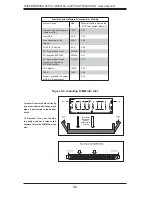
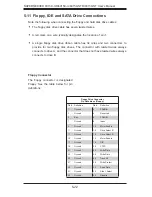
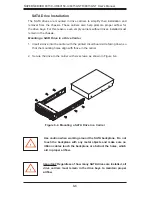
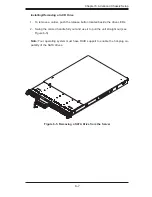
5-11 Floppy, IDE and SATA Drive Connections
Note the following when connecting the fl oppy and hard disk drive cables:
The fl oppy disk drive cable has seven twisted wires.
A red mark on a wire typically designates the location of pin 1.
A single fl oppy disk drive ribbon cable has 34 wires and two connectors to
provide for two fl oppy disk drives. The connector with twisted wires always
connects to drive A, and the connector that does not have twisted wires always
connects to drive B.
•
•
•
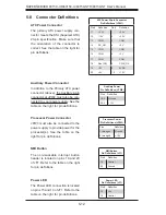
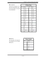
Floppy Connector
The fl oppy connector is designated
Floppy. See the table below for pin
defi nitions.
Floppy Drive Connector
Pin Defi nitions (Floppy)
Pin# Defi nition Pin # Defi nition
1
Ground
2
FDHDIN
3
Ground
4
Reserved
5
Key
6
FDEDIN
7
Ground
8
Index
9
Ground
10
Motor Enable
11
Ground
12
Drive Select B
13
Ground
14
Drive Select B
15
Ground
16
Motor Enable
17
Ground
18
DIR
19
Ground
20
STEP
21
Ground
22
Write Data
23
Ground
24
Write Gate
25
Ground
26
Track 00
27
Ground
28
Write Protect
29
Ground
30
Read Data
31
Ground
32
Side 1 Select
33
Ground
34
Diskette
Summary of Contents for SUPERSERVER 6015C-NT
Page 5: ...v Preface Notes ...
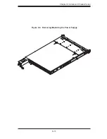
Page 69: ...Chapter 6 Advanced Chassis Setup 6 11 Figure 6 6 Removing Replacing the Power Supply ...
Page 70: ...6 12 SUPERSERVER 6015C UR 6015C U 6015C NTR 6015C NT User s Manual Notes ...
Page 100: ...A 6 SUPERSERVER 6015C UR 6015C U 6015C NTR 6015C NT User s Manual Notes ...
Page 106: ...B 6 SUPERSERVER 6015C UR 6015C U 6015C NTR 6015C NT User s Manual Notes ...
Page 110: ...C 4 SUPERSERVER 6015C UR 6015C U 6015C NTR 6015C NT User s Manual Notes ...


