14
SuperServer 5039MD(8/18)-H8TNR User's Manual
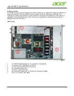
Figure 1-6. Motherboard Layout
1.5 Motherboard Layout
Below is a layout of the X11SDD-(8/18)C-F motherboard with jumper, connector and LED
locations shown. See the table on the following page for descriptions. For detailed descriptions,
pinout information and jumper settings, refer to Chapter 4.
JPWR1
JT
AG1
JRK1
JBT1
+
BT1
JTPM1
BMC_HB_LED1
J26
PRESS FIT
C
A
LED2
LED3
A C
FAN1
SW1
MH4
MH8
MH3
MH9
MH7
SAS1
SAS0
S-SGPIO1
MH5
MH6
MH2
MH1
JWD1
SRW10
SRW11
SRW12
SRW5
SRW6
SRW7
SRW8
SRW9
JKVM1
J3
J2
J20
X11SDD-8C-F
REV:1.02
DESIGNED IN USA
DIMMB1
DIMMA1
DIMME1 DIMMD1
CPU MICRO-LP
PCI-E 3.0 X8
M.2-H
M.2-H
CPU SLOT
PCI-E 3.0 X16
USB0/1
UID
CPU
S/N CODE
IPMI CODE
BIOS
LICENSE
S/N LABEL
JPME2
UID
FAN1
DIMMB1
DIMMA1
BT1
JRK1
JPWR1
DIMME1
DIMMD1
JWD1
S-SGPIO1
JKVM1
USB0/1
JPME2
SW1
LED2
SRW9
SAS1
JTPM1
JBT1
SAS0
SRW5
SRW8
SRW12
SRW7
SRW11
SRW6
SRW10
MICRO-LP
LED3
J3 - M.2
J2 - M.2
PCI-E SLOT