


Chapter 2: Installation
2-21
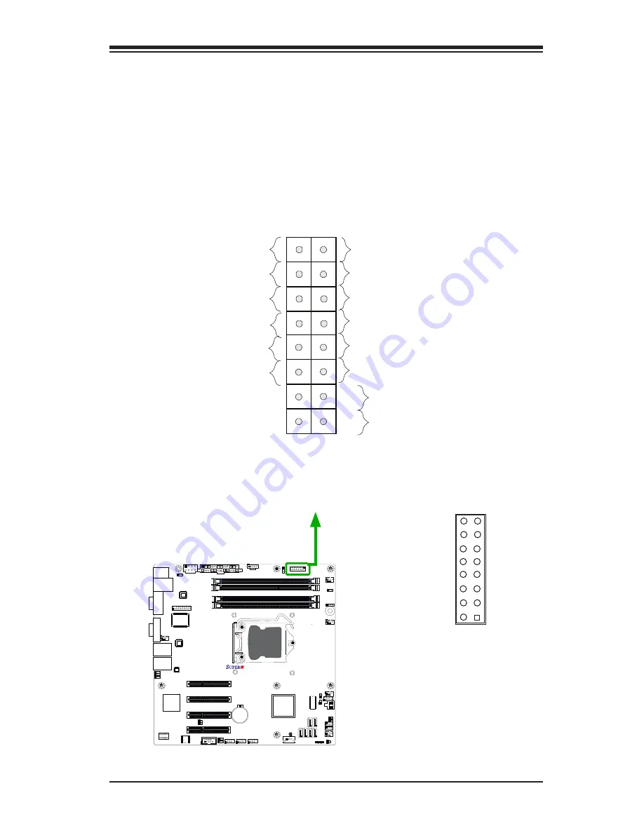
Front Control Panel
JF1 contains header pins for various buttons and indicators that are normally lo
-
cated on a control panel at the front of the chassis. These connectors are designed
specifically for use with Supermicro server chassis. See the figure below for the
descriptions of the various control panel buttons and LED indicators. Refer to the
following section for descriptions and pin definitions.
Pin 15
Pin 16
Pin 1
Pin 2
X9SCM/X9SCL(-F)
Rev.1.0
JF1 Header Pins
Power Button
OH/Fan Fail LED
1
NIC1 LED
Reset Button
2
HDD LED
Power LED
Reset
PWR
LE
LE
LE
UID LED
Ground
Ground
Power Fail LED
NIC2 LED
LE
LE
Summary of Contents for Supero X9SCL+-F
Page 1: ...USER S MANUAL Revision 1 2 X9SCM X9SCM F X9SCL X9SCL F X9SCL F...
Page 72: ...3 8 X9SCM X9SCM F X9SCL X9SCL F X9SCL F User s Manual Notes...
Page 94: ...4 22 X9SCM X9SCM F X9SCL X9SCL F X9SCL F Notes...
Page 96: ...A 2 X9SCM X9SCM F X9SCL X9SCL F X9SCL F User s Manual Notes...
Page 100: ...B 4 X9SCM X9SCM F X9SCL X9SCL F X9SCL F User s Manual Notes...


