


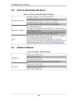


5-5
Chapter 5: Power Supply Modules
5-3
Power Components
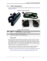
Power components for your system’s power supplies are shown below in
Figure 5-4
and
described in
Table 5-3
.
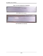
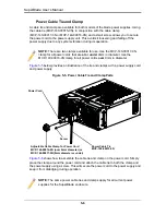
Figure 5-4. Power Components
Power Cord
Each 2000W power supply module has its own power cord with a C19 type connector
(IEC-60320-C19) to connect to the power supply. The power cord connects to a C20
type socket (IEC-60320-C20) for AC power on the power supply module. Each 1400W
power supply module has a C-14 type socket (IEC-60320-C14) for AC power and the
power cord must have a C-13 type connector (IEC-60320-C13) to connect to the power
supply. See
Figure 5-4
for an example of a power cord.
The plastic locking clip that partially covers the socket was designed to prevent the
power supply module from being removed with the power cord still connected.
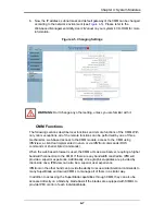
For details on the required power cord for your country, see the SuperMicro web site at:
http://www.supermicro.com/products/superblade/powersupply/powercord.cfm
Table 5-3. Power Components
Item
Name
Description
1
PDU
Power Distribution Unit (MCP-520-00036-0N)
2
Power Cable
Extension Cord (CBL-0223L)
3
AC Power Cord See
"Power Cord"
below for details.
2
1
3
Summary of Contents for SuperBlade Series
Page 1: ...SuperBlade User s Manual Revison 1 0c...
Page 4: ...SuperBlade User s Manual iv Notes...
Page 8: ...SuperBlade User s Manual viii Notes...
Page 10: ...SuperBlade User s Manual x Notes...
Page 12: ...SuperBlade User s Manual xii Notes...
Page 22: ...SuperBlade User s Manual 1 10 Notes...
Page 30: ...SuperBlade User s Manual 3 6 Figure 3 4 Enclosure Installed into Rack...
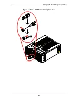
Page 53: ...5 7 Chapter 5 Power Supply Modules Figure 5 6 Power Cable Tie and Clamp Assembly...
Page 54: ...SuperBlade User s Manual 5 8 Notes...
Page 58: ...SuperBlade User s Manual A 4 Notes...