


32
Supermicro SCLA25 Chassis User's Manual
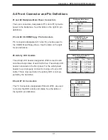
#8 and #9 Sideband Headers
The sideband headers are designated JP51 and JP52. For
SES-2 to work properly, you must connect an 8-pin side-
band cable. See the table to the right for pin definitions.
Sideband Headers
Pin # Definition
Pin # Definition
2
SGPIO: SDIN;
I
2
C: Backplane
Addressing
1
Controller ID
(SB6)
4
SGPIO: SD-
OUT; I
2
C: Reset
3
GND (SB2)
6
GND (SB3)
5
SGPIO:
SLOAD;
I
2
C: SDA
8
Backplane ID
(SB7)
7
SGPIO:
SCLOCK;
1
2
C: SCL
10
No Connection
9
No Connec-
tion
#12 to #19 SAS Ports
The SAS ports are used to connect the SAS drive cables.
The eight ports are designated #0 - #7. Each port is also
compatible with SATA drives.
#10 MG9072 Chip
The MG9072 is an enclosure management chip that sup-
ports the SES-2 controller and SES-2 protocols.
#11 Upgrade Header
The upgrade header is designated JP46 and is used for
manufacturing purposes only.