background image

C-3

Appendix D: SAS3-833A Backplane Specifications 

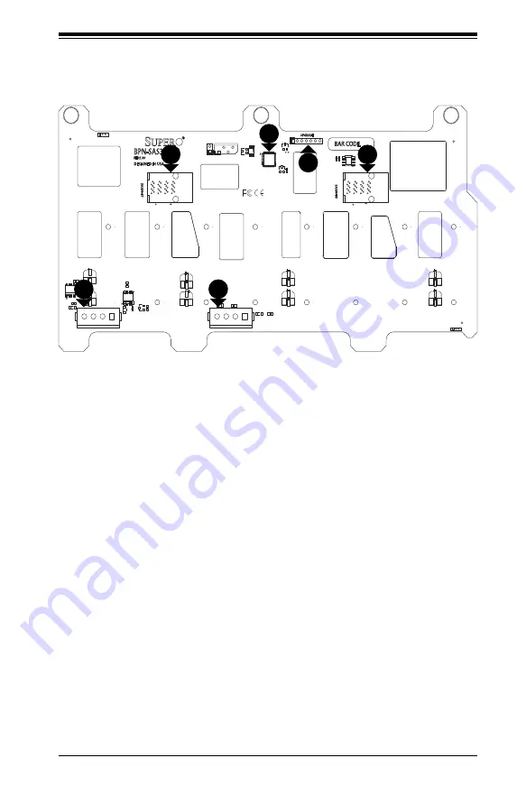
D-5  Front Connectors

Figure D-1: Front Components

1

1.  Chip: CPLD

2.  JTAG Connector (7-pin): J11, 

CPLD Upgrade Port

3.  MiniSAS HD Connector for Ports 

#4-7: JSM1

4.  MiniSAS HD Connector for Ports 

#0-3: JSM0

5.  Power Connector (4-pin) #1: 

JPW1

6.  Power Connector (4-pin) #2: 

JPW2

4

3

6

5

2

Summary of Contents for SC835 Series

Page 1: ...CSE 835TQ R800B CSE 835TQ R920B CSE 835TQC R802B CSE 835TQC R1K03B USER S MANUAL 1 0d SC835 Chassis Series ...

Page 2: ...D OR USED WITH THE PRODUCT INCLUDING THE COSTS OF REPAIRING REPLACING INTEGRATING INSTALLING OR RECOVERING SUCH HARDWARE SOFTWARE OR DATA Any disputes arising between manufacturer and customer shall be governed by the laws of Santa Clara County in the State of California USA The State of California County of Santa Clara shall be the exclusive venue for the resolution of any such disputes Super Mic...

Page 3: ...835 3U chassis features a unique and highly optimized design for dual core Xeon platforms The chassis is equipped with a redundant 800W high efficiency power supply High performance fans provide ample optimized cooling for FB DIMM memory modules and 8 hot swappable drive bays offer maximum storage capacity in a 3U form factor This document lists compatible parts available when this document was pu...

Page 4: ...ls on this chassis model including the fans bays airflow shields and other components Chapter 4 System Interface Chapter 4 provides details on the system interface which includes the functions and information provided by the control panel and other system LEDs Chapter 5 Chassis Setup and Maintenance Refer to this chapter for detailed information on this chassis Follow the procedures in this chapte...

Page 5: ...ion Warning 2 6 Equipment Installation 2 8 Restricted Area 2 9 Battery Handling 2 10 Redundant Power Supplies 2 12 Backplane Voltage 2 13 Comply with Local and National Electrical Codes 2 14 Product Disposal 2 15 Hot Swap Fan Warning 2 16 Power Cable and AC Adapter 2 18 Chapter 3 Chassis Components 3 1 Components 3 1 Drive Bays 3 1 Motherboard Support 3 1 Backplane 3 1 Power Supply 3 1 Fans 3 2 Ai...

Page 6: ...rmanent and Optional Standoffs 5 7 Standoff Labeling 5 7 Motherboard Installation Procedure 5 8 5 6 Installing Expansion Cards 5 9 5 7 Installing Cooling Elements 5 10 System Fans 5 11 Replacing a System Fan 5 11 Rear System Fans 5 12 Installing the Rear System Fans 5 12 Checking the Server Air Flow 5 13 5 8 Power Supply 5 14 Replacing the Power Supply 5 14 Replacing the Power Distributor 5 15 Cha...

Page 7: ... 833TQ Backplane C 2 C 5 Front Connectors and Jumpers C 3 Front Components C 3 C 6 Front Connector and Pin Definitions C 5 C 7 Front Jumper Locations and Pin Definitions C 7 Fan Jumper Settings C 8 I2 C and SGPIO Modes and Jumper Settings C 9 Front LED Indicators C 10 C 8 Rear Connectors and LED Indicators C 11 Appendix D SAS 833A Backplane Specifications D 1 ESD Safety Guidelines D 1 D 2 General ...

Page 8: ...SC835 Chassis Manual viii Notes ...

Page 9: ...about policies safety_information cfm 1 2 Shipping List Part Numbers Please visit the following link for the latest shipping lists and part numbers for your particular chassis model http www supermicro com products chassis 3U chs 835 SC835 Chassis Series Model HDD I O Slots Power Supply CSE C835TQ R800B 8x 3 5 SAS SATA hot swappable drive trays 7x FF 800W Redundant CSE 835TQ R920B 8x 3 5 SAS SATA ...

Page 10: ...uper Micro Computer B V Het Sterrenbeeld 28 5215 ML s Hertogenbosch The Netherlands Tel 31 0 73 6400390 Fax 31 0 73 6416525 Email sales supermicro nl General Information support supermicro nl Technical Support rma supermicro nl Customer Support Asia Pacific Address Super Micro Computer Inc 3F No 150 Jian 1st Rd Zhonghe Dist New Taipei City 235 Taiwan R O C Tel 886 2 8226 3990 Fax 886 2 8226 3991 W...

Page 11: ...must be mailed when service is complete For faster service RMA authorizations may be requested online http www super micro com support rma Whenever possible repack the chassis in the original Supermicro carton using the original packaging material If these are no longer available be sure to pack the chassis securely using packaging material to surround the chassis so that it does not shift within ...

Page 12: ...SC835 Chassis Manual 1 4 Notes ...

Page 13: ...mponents in the Supermicro chassis These warnings may also be found on our web site at http www supermicro com about policies safety_information cfm Warning This warning symbol means danger You are in a situation that could cause bodily injury Before you work on any equipment be aware of the hazards involved with electrical circuitry and be familiar with standard practices for preventing accidents...

Page 14: ...os riesgos de la corriente eléctrica y familiarícese con los procedimientos estándar de prevención de accidentes Al final de cada advertencia encontrará el número que le ayudará a encontrar el texto traducido en el apartado de traducciones que acompaña a este dispositivo GUARDE ESTAS INSTRUCCIONES IMPORTANTES INFORMATIONS DE SÉCURITÉ Ce symbole d avertissement indique un danger Vous vous trouvez d...

Page 15: ...LIGHEIDSINSTRUCTIES Dit waarschuwings symbool betekent gevaar U verkeert in een situatie die lichamelijk letsel kan veroorzaken Voordat u aan enige apparatuur gaat werken dient u zich bewust te zijn van de bij een elektrische installatie betrokken risico s en dient u op de hoogte te zijn van de standaard procedures om ongelukken te voorkomen Gebruik de nummers aan het eind van elke waarschuwing om...

Page 16: ...gen lesen Advertencia Lea las instrucciones de instalación antes de conectar el sistema a la red de alimentación Attention Avant de brancher le système sur la source d alimentation consulter les directives d installation 設置手順書 システムを電源に接続する前に 設置手順書をお読み下さい 시스템을 전원에 연결하기 전에 설치 안내를 읽어주십시오 Waarschuwing Raadpleeg de installatie instructies voordat u het systeem op de voedingsbron aansluit 警告 将此系统连接电源前 请...

Page 17: ... Sie sicher dass der Nennwert der Schutzvorrichtung nicht mehr als 250 V 20 A beträgt Advertencia Este equipo utiliza el sistema de protección contra cortocircuitos o sobrecorrientes del edificio Asegúrese de que el dispositivo de protección no sea superior a 250 V 20 A Attention Pour ce qui est de la protection contre les courts circuits surtension ce produit dépend de l installation électrique d...

Page 18: ... es auf den Chassisinnenraum zurückgreift um Systemsbestandteile anzubringen oder zu entfernen Warning The system must be disconnected from all sources of power and the power cord removed from the power supply module s before accessing the chassis interior to install or remove system components 경고 이 제품은 전원의 단락 과전류 방지에 대해서 전적으로 건물의 관련 설비에 의존합니다 보호장치의 정격이 반드시 250V 볼트 20A 암페어 를 초과하지 않도록 해야 합니다 Waarsc...

Page 19: ...re débranché de toutes les sources de puissance ainsi que de son cordon d alimentation secteur avant d accéder à l intérieur du chassis pour installer ou enlever des composants de systéme 경고 시스템에 부품들을 장착하거나 제거하기 위해서는 섀시 내부에 접근하기 전에 반드시 전원 공급장치로부터 연결되어있는 모든 전원과 전기코드를 분리해주어야 합니다 Waarschuwing Voordat u toegang neemt tot het binnenwerk van de behuizing voor het installeren of verwijderen van systeem o...

Page 20: ...ienen dieser Ausrüstung sollte nur geschultem qualifiziertem Personal gestattet werden Advertencia Solamente el personal calificado debe instalar reemplazar o utilizar este equipo Attention Il est vivement recommandé de confier l installation le remplacement et la maintenance de ces équipements à des personnels qualifiés et expérimentés 경고 훈련을 받고 공인된 기술자만이 이 장비의 설치 교체 또는 서비스를 수행할 수 있습니다 警告 只有经过培训且...

Page 21: ...in Bereichen mit beschränktem Zutritt vorgesehen Der Zutritt zu derartigen Bereichen ist nur mit einem Spezialwerkzeug Schloss und Schlüssel oder einer sonstigen Sicherheitsvorkehrung möglich Advertencia Esta unidad ha sido diseñada para instalación en áreas de acceso restringido Sólo puede obtenerse acceso a una de estas áreas mediante la utilización de una herramienta especial cerradura con llav...

Page 22: ...도구 잠금 장치 및 키 또는 기타 보안 수단을 통해서만 접근 제한 구역에 들어갈 수 있습니다 Waarschuwing Dit apparaat is bedoeld voor installatie in gebieden met een beperkte toegang Toegang tot dergelijke gebieden kunnen alleen verkregen worden door gebruik te maken van speciaal gereedschap slot en sleutel of andere veiligheidsmaatregelen 電池の取り扱い 電池交換が正しく行われなかった場合 破裂の危険性があります 交換する電池はメー カーが推奨する型 または同等のものを使用下さい 使用済電池は製造元の指示に従 って処分して下さい 警...

Page 23: ...formément aux instructions du fabricant Advertencia Existe peligro de explosión si la batería se reemplaza de manera incorrecta Reemplazar la batería exclusivamente con el mismo tipo o el equivalente recomendado por el fabricante Desechar las baterías gastadas según las instrucciones del fabricante 경고 배터리가 올바르게 교체되지 않으면 폭발의 위험이 있습니다 기존 배터리와 동일하거나 제조사에서 권장하는 동등한 종류의 배터리로만 교체해야 합니다 제조사의 안내에 따라 사용된 배...

Page 24: ... desconectarse todas las conexiones Attention Cette unité peut avoir plus d une connexion d alimentation Pour supprimer toute tension et tout courant électrique de l unité toutes les connexions d alimentation doivent être débranchées Redundant Power Supplies Warning This unit might have more than one power supply connection All connections must be removed to de energize the unit 冗長電源装置 このユニッ トは複数の...

Page 25: ... el voltaje del plano trasero es peligroso Tenga cuidado cuando lo revise Attention Lorsque le système est en fonctionnement des tensions électriques circulent sur le fond de panier Prendre des précautions lors de la maintenance Warning Hazardous voltage or energy is present on the backplane when the system is operating Use caution when servicing 경고 이 장치에는 한 개 이상의 전원 공급 단자가 연결되어 있을 수 있습니다 이 장치에 전원...

Page 26: ...lation der Geräte muss den Sicherheitsstandards entsprechen Advertencia La instalacion del equipo debe cumplir con las normas de electricidad locales y nacionales 경고 시스템이 동작 중일 때 후면판 Backplane 에는 위험한 전압이나 에너지가 발생 합니다 서비스 작업 시 주의하십시오 Waarschuwing Een gevaarlijke spanning of energie is aanwezig op de backplane wanneer het systeem in gebruik is Voorzichtigheid is geboden tijdens het onderhoud 警告 设备安装...

Page 27: ...ormément aux normes électriques nationales et locales 경고 현 지역 및 국가의 전기 규정에 따라 장비를 설치해야 합니다 Waarschuwing Bij installatie van de apparatuur moet worden voldaan aan de lokale en nationale elektriciteitsvoorschriften 製品の廃棄 この製品を廃棄処分する場合 国の関係する全ての法律 条例に従い処理する必要が あります 警告 本产品的废弃处理应根据所有国家的法律和规章进行 警告 本產品的廢棄處理應根據所有國家的法律和規章進行 Warnung Die Entsorgung dieses Produkts sollte gemäß allen Bestimmungen und Gesetzen...

Page 28: ...duit sont généralement soumis à des lois et ou directives de respect de l environnement Renseignez vous auprès de l organisme compétent Warning The fans might still be turning when you remove the fan assembly from the chassis Keep fingers screwdrivers and other objects away from the openings in the fan assembly s housing Hot Swap Fan Warning ファン ホッ トスワップの警告 シャーシから冷却ファン装置を取り外した際 ファンがまだ回転している可能性がありま...

Page 29: ...tilador Attention Il est possible que les ventilateurs soient toujours en rotation lorsque vous retirerez le bloc ventilateur du châssis Prenez garde à ce que doigts tournevis et autres objets soient éloignés du logement du bloc ventilateur 경고 섀시로부터 팬 조립품을 제거할 때 팬은 여전히 회전하고 있을 수 있습니다 팬 조림품 외관의 열려있는 부분들로부터 손가락 및 스크류드라이버 다른 물체들이 가까이 하지 않도록 배치해 주십시오 Waarschuwing Het is mogelijk dat de ventilator nog ...

Page 30: ...er Code für alle anderen elektrischen Geräte als Produkte von Supermicro nur bezeichnet gezeigt haben Advertencia Al instalar el producto utilice los cables de conexión previstos o designados los cables y adaptadores de CA La utilización de otros cables y adaptadores podría ocasionar un mal funcionamiento o un incendio Aparatos Eléctricos y la Ley de Seguridad del Material prohíbe el uso de UL o C...

Page 31: ...cro seulement 경고 제품을 설치할 때에는 제공되거나 지정된 연결케이블과 전원케이블 AC어댑터를 사용해야 합니다 그 밖의 다른 케이블들이나 어댑터들은 고장 또는 화재의 원인이 될 수 있습니다 전기용품안전법 Electrical Appliance and Material Safety Law 은 슈퍼마이크로에서 지정한 제품들 외에는 그 밖의 다른 전기 장치들을 위한 UL또는 CSA에서 인증한 케이블 전선 위에 UL CSA가 표시 들의 사용을 금지합니다 Waarschuwing Bij het installeren van het product gebruik de meegeleverde of aangewezen kabels stroomkabels en adapters Het gebruik van andere ka...

Page 32: ...2 20 SC835 Chassis Manual Notes ...

Page 33: ...hat can house additional hard drives removable media drives or other peripheral drives A slim DVD drive One additional vertically oriented bay for a peripheral drive or fixed hard disk drive Motherboard Support The maximum motherboard size is 13 68 x 13 supporting Intel and AMD Quad processors Refer to www supermicro com for updates Backplane The chassis comes with a backplane for SAS or SATA driv...

Page 34: ...rs and a chassis intrusion switch Mounting Rails Rails for mounting your chassis in a rack are included 3 2 Unpacking the System Inspect the box in which the chassis was shipped and note if it was damaged If the chassis itself shows damage file a damage claim with the carrier 3 3 Where to get Replacement Components Infrequently you may need replacement parts for your system To ensure the highest l...

Page 35: ...d others on the drive carriers to keep you informed of the overall status of the system and the activity and health of specific components The chassis control panel includes a reset button and an on off switch This chapter explains the meanings of the LED indicators and the appropriate responses Figure 4 1 Front Panel ...

Page 36: ...eset The reset button is used to reboot the system Power The main power switch is used to apply or remove power from the power supply to the server system Turning off system power with this button removes the main power but keeps standby power supplied to the system Therefore you must unplug system before servicing ...

Page 37: ...An overheat condition has occured This may be caused by cable congestion Blinking red 1Hz Fan failure check for an inoperative fan Blinking red 0 25Hz Power failure check for a non operational power supply Solid blue Local UID has been activated Use this function to locate the server in a rack mount environment Blinking blue Remote UID is on Use this function to identify the server from a remote l...

Page 38: ...s LED to blink on and off when that particular drive is being accessed Red The red LED indicates a drive failure If a SAS drive fails your system management software should alert you Power Indicates power is being supplied to the system s power supply units This LED should normally be illuminated when the system is operating HDD Indicates IDE channel activity SAS SATA drive and or DVD ROM drive ac...

Page 39: ...d with an SAS 833TQ backplane this chassis is capable of failover and cascading Review Appendix C in this manual for setup instructions 5 2 Removing the Power Cord Before performing most setup or maintenance tasks use the following procedure to ensure that power has been removed from the system 1 Use the operating system to power down the node following the on screen prompts 2 After the system has...

Page 40: ...move the chassis cover screw 2 Once the top cover is released from the locked position slide the cover toward the rear of the chassis and lift the cover off the unit Caution Except for short periods of time do not operate the server without the cover in place The chassis cover must be in place to allow proper airflow and prevent overheating Figure 5 1 Removing the Chassis Cover Release Tab Cover S...

Page 41: ...s or removable media drives Installing 3 5 Hard Drives The drives are mounted in drive carriers to simplify their installation and removal from the chassis SAS or enterprise grade SATA is recommended Removing the Hard Drive Carriers 1 Press the release button on the drive carrier This extends the drive carrier handle 2 Use the handle to pull the drive carrier out of the chassis Figure 5 2 Removing...

Page 42: ...carrier 2 Lift the dummy drive out of the drive carrier Figure 5 3 Removing the Dummy Drive from the Carrier Note Only enterprise level hard disk drives are recommended For recommended HDDs visit the Supermicro Web site at http www supermicro com products nfo files storage SAS 1 CompList 110909 pdf Drive Carrier Release Button 1 1 1 2 ...

Page 43: ...ace such as a desk or work bench 4 Slide the hard drive into the carrier with the printed circuit board side facing down 5 Carefully align the mounting holes in the hard drive and the carrier Make sure the bottom of the hard drive and bottom of the hard drive carrier are flush 6 Secure the hard drive using all six screws 7 Replace the drive carrier into the chassis Make sure to close the drive car...

Page 44: ...g the Slim DVD Drive The chassis supports a slim DVD drive just under the control panel 1 Power down the system as described in Section 5 2 and remove the cover 2 If a new front port panel is not being installed remove the mini bezel from the drive bay The mini bezel is the small grating that covers the drive bay Remove this by simply pulling it out of the bay If a new front port panel is being in...

Page 45: ...ts or non standard security Optional standoffs are included to these motherboards To use an optional standoff you must secure a hexagonal post by screwing it into the necessary spot Standoff Labeling Standoff locations are labeled on the bottom of the chassis with the letters P D and A P Most compatible motherboards have a processor or CPU located here If neces sary place standoffs here for the CP...

Page 46: ...ll the I O shield that accompanies your motherboard on the rear of the chassis 5 If required by your motherboard install standoffs in any areas that do not have a permanent standoff To do this tighten a hexagonal optional standoff into the chassis 6 Lay the motherboard on the chassis aligning the permanent and optional standoffs 7 Secure the motherboard to the chassis using the rounded Phillips he...

Page 47: ...xpansion card into the correct motherboard slot If the expan sion card requires a riser card install it at this time If necessary slide the card into the PCI card guide and lock it Never force a component into a motherboard or the chassis 5 Secure the expansion card with the screw from the I O panel 5 6 Installing Expansion Cards The chassis includes space for up to seven expansion cards Figure 5 ...

Page 48: ... removed prior to installing the air shroud Installing the Air Shroud 1 Check that the rear fans have been removed from the chassis 2 Place the air shroud over the motherboard as illustrated above aligning the air shroud between the front and rear fans 3 Install the rear fans behind the air shroud See the Rear System Fans section of this chapter for additional details Figure 5 8 Installing the Air...

Page 49: ...placing a System Fan Installing a System Fan 1 Open the chassis and locate the faulty fan Never run the chassis for an extended period of time with the chassis open 2 Press the release tab on the fan and pull the fan upward 3 Slide the new fan into the fan housing Make sure the power connectors are correctly aligned The new fan will be immediately active Figure 5 9 Chassis Fans Front Fan 3 total R...

Page 50: ...s Installing a the Rear System Fans 1 Confirm that the air shroud is correctly placed 2 Slide the rear fan into the slot as illustrated The fan release tab should be on the side closest to the power supply 3 Make sure that the fan is secure in the fan housing and the housing is correctly connected to the power supply Figure 5 10 Installing the Rear Fan ...

Page 51: ...es through the cable rack 2 Do not operate the chassis without drives or drive trays in the drive bays 3 Use only recommended server parts 4 Make sure no wires or foreign objects obstruct air flow through the chassis Pull all excess cabling out of the airflow path or use shorter cables 5 Do not operate the server for extended periods of time without the air shroud in the proper place ...

Page 52: ...tinue running if only one power supply module is removed at a time 2 Unplug the power supply that will be replaced 3 Push the release tab on the back of the power supply 4 Pull the power supply out using the handle 5 Replace the failed power module with another of the same model 6 Push the new power supply module into the power bay until it clicks into the locked position 7 Plug the AC power cord ...

Page 53: ...otherboard back plane and other components Also remove both power supplies 3 Locate the power distributor between the power supply and the fan row 4 Remove the three screws securing the power supply 5 Gently pull the power distributor from the chassis Guide the cables through the power distributor housing 6 Slide the new power distributor module into the power distributor housing Slide the cables ...

Page 54: ...SC835 Chassis Manual 5 16 Notes ...

Page 55: ...ave approximately 30 inches of clearance in the back of the rack to allow for sufficient airflow and ease in servicing Install in a restricted access location such as a dedicated equipment room or service closet Ambient Operating Temperature If installed in a closed or multi unit rack assembly the ambient operating tempera ture of the rack environment may be greater than the ambient temperature of...

Page 56: ...e attached to the rack In multiple rack installations the racks should be coupled together When mounting this unit in a partially filled rack load the rack from the bottom to the top with the heaviest component at the bottom of the rack If this is the only unit in the rack mount it at the bottom Always make sure the rack is stable before extending a component from the rack Extend only one componen...

Page 57: ...odules to cool before touching them Always keep the rack front door all panels and all components on the servers closed when not servicing to maintain proper cooling Warning Do not pick up the server by the front handles They are designed to pull the system from a rack only ...

Page 58: ...k between 26 and 33 5 deep Identifying the Sections of the Rack Rails The chassis package includes two rail assemblies in the rack mounting kit Each assembly consists of three sections an inner chassis rail which secures directly to the chassis an outer rail that secures to the rack and a middle rail which extends from the outer rail These assemblies are specifically designed for the left and righ...

Page 59: ... in place when fully extended from the rack This prevents the server from coming completely out of the rack when the chassis is pulled out for servicing Releasing the Inner Rail Releasing Inner Rail from the Outer Rails 1 Identify the left and right outer rail assemblies 2 Pull the inner rail out of the outer rail until it is fully extended as illustrated below 3 Press the locking tab down to rele...

Page 60: ...tified 2 Place the inner rail firmly against the side of the chassis aligning the hooks on the side of the chassis with the holes in the inner rail 3 Slide the inner rail forward toward the front of the chassis until the rail clicks into the locked position which secures the inner rail to the chassis 4 Secure the inner rail to the chassis with the screw provided 5 Repeat for the other inner rail 1...

Page 61: ... use screws to secure the outer rails to the rack as illustrated above 4 Pull out the rear of the outer rail adjusting the length until it fits within the posts of the rack 5 Hang the hooks of the rear portion of the outer rail onto the slots on the rear of the rack If necessary use screws to secure the rear of the outer rail to the rear of the rack 6 Repeat steps 1 5 for the remaining outer rail ...

Page 62: ...iddle rail 4 Align the chassis inner rails with the front of the middle rails 5 Slide the inner rails on the chassis into the middle rails keeping the pressure even on both sides until the locking tab of the inner rail clicks into the front of the middle rail locking the chassis into the fully extended position 6 Depress the locking tabs of both sides at the same time and push the chassis all the ...

Page 63: ...ons For more compatible cables refer to the manufacturer of the motherboard you are using and our Web site at www supermicro com A 2 Cables Included with SC835TQ Chassis SAS SATA SC835TQ R800B Part Type Length Description CBL 0044L Cable 2 SATA cable CBL 0087 Ribbon Round 20 16 pin to 16 pin ribbon cable for control panel CBL 0209L Wire 210mm 4 pin to 3 pin fan power cable Cable 6 Regional power c...

Page 64: ...sas connector 36 pins at one end and 4 SAS connectors on one end This cable connects from the Host motherboard or other controller to the backplane SAS hard drive port Cable Name SAS Cable Quantity 1 Part CBL 0116 Alt Name iPass or Small Four A 3 Compatible Cables This section lists cables included with the SC835 Chassis packages Alternate SAS Cables Some compatible motherboards have different con...

Page 65: ...Host Bus Adapter HBA or external port Used in Dual port environments Cable Name SAS Cable Quantity varies by setup Part CBL 0168L Ports Dual Placement Internal cable Description Internal cable Connects the backplane to the Host Bus Adapter HBA or external port Used in single port environments Cable Name SAS Cable Quantity varies by setup Part CBL 0167L Ports Single Placement Internal cable ...

Page 66: ...ding cable Connects ports between servers With most connectors use one cable for single port connections and two cables for dual port connections Cable Name SAS Cable Quantity varies by setup Part CBL 0166L Ports Single or Dual Placement External cable ...

Page 67: ...0 pin CBL 0059 7 9 20 CM 8 pin CBL 0062 7 9 20 CM 4 pin CBL 0060 7 9 20 CM Front Panel to the Motherboard The SC835 chassis includes a cable to connect the chassis front panel to the motherboard If your motherboard uses a different connector use the following list to find a compatible cable Front Panel to Motherboard Cable Ribbon Cable Number of Pins Front Panel Number of Pins Motherboard Cable Pa...

Page 68: ...SC835 Chassis Manual A 6 Notes ...

Page 69: ...assis system CSE 835TQ R800B 800W Redundant MFR Part PWS 801 1R Rated AC Voltage 100 240V 50 60Hz 10A 4 Amp 5V standby 4 Amp 12V 66 Amp 5V 25 Amp 3 3V 12 Amp 12V 0 5 Amp CSE 835TQ R920B 920W Redundant MFR Part PWS 920P 1R Rated AC Voltage 100 240V 50 60Hz 11 4 5 Amp 5V standby 4 Amp 12V 75 Amp 5V 30 Amp 3 3V 24 Amp 12V 0 6 Amp ...

Page 70: ...rt PWS 802A 1R Rated AC Voltage 100 240V 10 5A 200 240V 5A 50 60Hz 11 4 5 Amp 5V standby 4A 12V 66A 5V N A 3 3V N A 12V N A CSE 835TQ R1K03B 1000W Redundant MFR Part PWS 1K03A 1R Rated AC Voltage 200 240V 50 60Hz 5V standby 4 Amp 12V 83 Amp 5V N A 3 3V N A 12V N A ...

Page 71: ...able 2 motherboard Provides power to the motherboard CPU This cable has two black and two yellow wires 4 pin mother board cable 1 motherboard Provides power to PCI expansion card This cable has two black and two yellow wires 5 pin SMBus power cable small 1 motherboard Allows the SM System Manage ment bus to monitor power supply 2 pin INT cable 1 motherboard Intrusion detection cable allows the sys...

Page 72: ...to prevent static discharge Touch a grounded metal object before removing a component from the antistatic bag Handle the backplane by its edges only do not touch its components peripheral chips memory modules or gold contacts When handling chips or modules avoid touching their pins Put the card and peripherals back into their antistatic bags when not in use C 2 General Safety Guidelines Always dis...

Page 73: ...ics shown in this manual C 4 Introduction to the SAS 833TQ Backplane The SAS 833TQ backplane has been designed to utilize the most up to date tech nology available providing your system with reliable high quality performance This manual reflects SAS 33TQ Revision 3 0 the most current release available at the time of publication Always refer to the Supermicro website at www supermicro com for the l...

Page 74: ... C Connector 1 JP37 and I2 C Connector 2 JP95 3 Sideband Connector 1 JP66 and Sideband Connector 2 JP68 4 Chip MG9072 5 Power Connectors 4 pin JP10 and JP13 6 Fan Connectors JP54 JP56 and JP60 7 ACT_IN JP26 8 SAS Port 0 J5 9 SAS Port 1 J6 Buzzer Figure C 1 Front Components 1 1 1 9 1 8 1 7 1 6 1 6 1 6 1 5 1 5 1 4 1 3 1 2 1 2 1 10 1 12 1 13 1 14 1 15 1 11 1 3 ...

Page 75: ...C 4 SC835 Chassis Manual 10 SAS Port 2 J7 11 SAS Port 3 J8 12 SAS Port 4 J10 13 SAS Port 5 J12 14 SAS Port 6 J14 15 SAS Port 7 J16 ...

Page 76: ...4 No Connection 1 Upgrade Connector The upgrade connector designated JP69 is used for manufacturer s diagnostic purposes only 3 Sideband Headers The sideband headers are designated JP66 and JP68 For SES 2 to work properly you must connect an 8 pin sideband cable See the table to the right for pin definitions NOTE SGPIO is the default setting for this backplane Sideband Headers Pin Definition Pin D...

Page 77: ...in Definition 1 Ground 2 12V 3 Tachometer SAS Activity LED Header Pin Definitions Pin Definition Pin Definition 1 ACT IN 0 6 ACT IN 4 2 ACT IN 1 7 ACT IN 5 3 ACT IN 2 8 ACT IN 6 4 ACT IN 3 9 ACT IN 7 5 Ground 10 Empty 7 Activity LED Header The activity LED header designated JP26 is used to indicate the activity status of each SAS drive The Activity LED Header is located on the front panel For the ...

Page 78: ...o choose between optional settings Jumpers create shorts between two pins to change the function of the connector Pin 1 is identified with a square solder pad on the printed circuit board Note On two pin jumpers Closed means the jumper is on and Open means the jumper is off the pins Connector Pins Jumper Setting 3 2 1 3 2 1 JP63 JP62 JP99 JP98 JP97 JP35 JP61 Figure C 2 Jumper Locations ...

Page 79: ...zer alarm is triggered by the following conditions 1 Hard drive failure 2 Fan failure 3 System temperature over 45º Celsius Fan Jumper Settings This backplane can use up to three fans To utilize each fan you must configure both jumpers as instructed below Fan Jumper Settings Jumper Jumper Settings Note JP61 1 2 With fan 2 3 No fan FAN 1 select JP97 1 2 With fan 2 3 No fan FAN 1 select JP62 1 2 Wit...

Page 80: ...SGPIO is the default mode and can be used without making changes to your jumpers The following information details which jumpers must be configured to use I2 C mode or restore your backplane to SGPIO mode SGPIO and I2 C Jumper Settings Default Jumper SGPIO Jumper Setting Default I2 C Jumper Setting Note JP84 1 2 2 3 Controller ID 1 ...

Page 81: ...fail Off Failure in Fan 2 Fan 3 fail Off Failure in Fan 3 Alarm 1 Off Overheat drive failure 5V On Backplane power failure Light is on during normal operation 12V On Backplane power failure Light is on during normal operation Front LED Indicators ALARM LED 12V LED FAN FAIL 1 2 3 LEDs 5V LED Figure C 3 Front LEDs ...

Page 82: ... SAS SATA HDD 4 SAS 5 SAS SATA HDD 5 SAS 6 SAS SATA HDD 6 SAS 7 SAS SATA HDD 7 Rear LED Indicators Rear LED Hard Drive Activity Failure LED SAS 0 D12 D5 SAS 1 D13 D6 SAS 2 D14 D7 SAS 3 D15 D8 SAS 4 D18 D19 SAS 5 D21 D20 SAS 6 D22 D23 SAS 7 D24 D29 8 1 8 1 8 1 8 1 8 1 8 1 8 1 8 8 1 D22 D23 SAS 0 J1 SAS 1 J2 SAS 2 J3 SAS 3 J4 SAS 4 J9 SAS 5 J11 SAS 6 J13 SAS 7 J15 D12 D5 D13 D6 D14 D7 D15 D8 D18 D19...

Page 83: ... reasonably expected to result in significant injury or loss of life or catastrophic property damage Accordingly Supermicro disclaims any and all liability and should buyer use or sell such products for use in such ultra hazardous applications it does so entirely at its own risk Furthermore buyer agrees to fully indemnify defend and hold Supermicro harmless for and against any and all claims deman...

Page 84: ...to prevent static discharge Touch a grounded metal object before removing a component from the antistatic bag Handle the backplane by its edges only do not touch its components peripheral chips memory modules or gold contacts When handling chips or modules avoid touching their pins Put the card and peripherals back into their antistatic bags when not in use D 2 General Safety Guidelines Always dis...

Page 85: ...ics shown in this manual D 4 Introduction to the SAS3 833A Backplane The SAS3 833A backplane has been designed to utilize the most up to date tech nology available providing your system with reliable high quality performance This manual reflects SAS 33TQ Revision 1 0 the most current release available at the time of publication Always refer to the Supermicro website at www supermicro com for the l...

Page 86: ...ont Connectors Figure D 1 Front Components 1 1 Chip CPLD 2 JTAG Connector 7 pin J11 CPLD Upgrade Port 3 MiniSAS HD Connector for Ports 4 7 JSM1 4 MiniSAS HD Connector for Ports 0 3 JSM0 5 Power Connector 4 pin 1 JPW1 6 Power Connector 4 pin 2 JPW2 4 3 6 5 2 ...

Page 87: ...pin definitions 3 4 MiniSAS HD Connectors The SAS ports are used to connect the SAS drive cables The 2 ports are designated JSM0 for drives at SAS 0 3 and JSM1 for drives at SAS 4 7 see section 2 4 for SAS drive loca tions Each port is also compatible with SATA drives However mixing SAS3 and SATA drives in the same enclosure is not recommended 1 CPLD Chip The CPLD is an enclosure management chip t...

Page 88: ...optional settings Jumpers create shorts between two pins to change the function of the connector Pin 1 is identified with a square solder pad on the printed circuit board Note On two pin jumpers Closed means the jumper is on and Open means the jumper is off the pins Connector Pins Jumper Setting 3 2 1 3 2 1 Jumper Settings Jumper Jumper Settings Note ACTLED Open Default This is used for internal t...

Page 89: ...in Definition 1 Ground 2 12V 3 Tachometer SAS Activity LED Header Pin Definitions Pin Definition Pin Definition 1 ACT IN 0 6 ACT IN 4 2 ACT IN 1 7 ACT IN 5 3 ACT IN 2 8 ACT IN 6 4 ACT IN 3 9 ACT IN 7 5 Ground 10 Empty 7 Activity LED Header The activity LED header designated JP26 is used to indicate the activity status of each SAS drive The Activity LED Header is located on the front panel For the ...

Page 90: ...o choose between optional settings Jumpers create shorts between two pins to change the function of the connector Pin 1 is identified with a square solder pad on the printed circuit board Note On two pin jumpers Closed means the jumper is on and Open means the jumper is off the pins Connector Pins Jumper Setting 3 2 1 3 2 1 JP63 JP62 JP99 JP98 JP97 JP35 JP61 Figure D 3 Jumper Locations ...

Page 91: ...17 LED22 LED21 LED11 LED20 LED10 LED8 LED7 SAS SATA Connectors and LED Indicators Rear Connector SAS Drive Number Failure LED Activity LED J1 SAS SATA HDD 0 LED6 LED0 J2 SAS SATA HDD 1 LED7 LED1 J3 SAS SATA HDD 2 LED8 LED16 J4 SAS SATA HDD 3 LED10 LED14 J5 SAS SATA HDD 4 LED20 LED15 J12 SAS SATA HDD 5 LED11 LED17 J13 SAS SATA HDD 6 LED21 LED18 J14 SAS SATA HDD 7 LED22 LED19 ...

Reviews: